Special operating lever for live installation of bird repellent
A bird repellent and operating lever technology, which is applied to overhead lines/cable equipment, etc., can solve the problems of operators safely burying major hidden dangers and high working intensity, improving continuous stability, improving service levels, reducing processing difficulty and The effect of assembly and debugging difficulty
- Summary
- Abstract
- Description
- Claims
- Application Information
AI Technical Summary
Problems solved by technology
Method used
Image
Examples
Embodiment approach 1
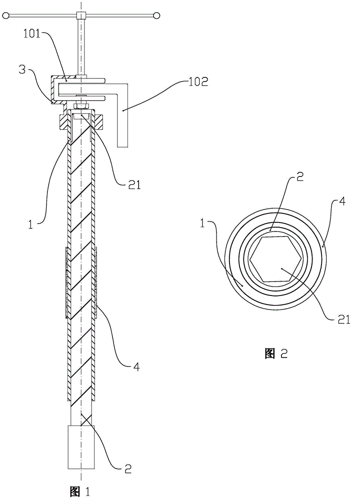
[0031] The special operating rod for live installation of the bird repellent includes a sleeve rod 1, a rotating rod 2 and a fixed part 3. The sleeve rod 1 is provided with an axial cavity, and threads are arranged on the inner wall of the cavity. An anti-slip rubber sleeve 4 is provided at the middle and lower part of the outer wall of the sleeve rod 1 . The rotating rod 2 is coaxially assembled in the axial inner cavity of the sleeve rod 1 through a threaded connection structure, and the axial length of the rotating rod 2 is greater than the axial length of the sleeve rod 1 .
[0032]An axial counterbore 21 is arranged on the upper end surface of the rotary rod 2, at least the lower part of the inner cavity of the counterbore 21 is formed as a hexagonal cavity. As shown in Figures 1 and 2, the axial length of the counterbore 21 on the upper end surface of the rotary rod 2 is 0.8 times the axial thickness of the bolt and nut on the U-shaped seat 101 of the bird repellent. T...
Embodiment approach 2
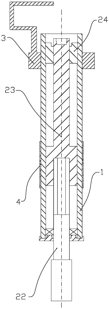
[0036] It differs from Embodiment 1 in that the structure of the rotating rod 2 and the assembly form between the rotating rod 2 and the sleeve rod 1 are changed. Specifically:
[0037] The rotary rod 2 includes a driving rod 22 and a lifting rod 23 , and the counterbore 21 is arranged on an upper surface of the lifting rod 23 . The lower end surface of the lifting rod 23 is provided with an axial threaded blind hole. The upper end of the driving rod 22 is matched with the threaded blind hole at the lower end of the elevating rod 23 . The drive rod 22 cooperates with the lower port of the sleeve rod 1 through a bearing. A screw sleeve 24 coaxial with the sleeve rod 1 is fixedly arranged on the upper end of the cavity of the sleeve rod 1 . The outer wall of the upper end of the lifting rod 23 cooperates with the screw sleeve 24, and the cooperation form between the lifting rod 23 and the screw sleeve 24 adopts a ball screw nut structure. The outer diameter of the lower end ...
Embodiment approach 3
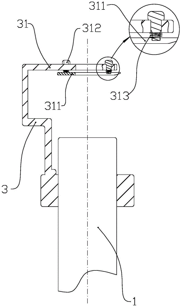
[0040] Compared with the first two installation methods, the improvement mainly lies in the top plate 31 of the U-shaped bayonet on the clamping part of the fixing part 3 . Specifically:
[0041] The fixing part also includes a pressing plate 311 and a plurality of connecting bolts 312 . The right end of the top plate 31 of the U-shaped bayonet on the clamping part of the fixing part 3 extends rightward relative to the axis of the sleeve rod 1 .
[0042] In the middle of the top plate 31 , a notch extending left and right is provided from the right end of the top plate 31 .
[0043] On the top plate, a row of two through holes are respectively arranged on the front side and the rear side of the notch.
[0044] On the pressing plate 311, corresponding to the notch and the through hole on the top plate 31, corresponding notches and threaded holes are set, and the front and rear width of the notch on the pressing plate 311 is not less than that on the top plate 31. The front-t...
PUM
 Abstract
Description
Claims
Application Information
 - R&D
- Intellectual Property
- Life Sciences
- Materials
- Tech Scout
- Unparalleled Data Quality
- Higher Quality Content
- 60% Fewer Hallucinations
Browse by: Latest US Patents, China's latest patents, Technical Efficacy Thesaurus, Application Domain, Technology Topic, Popular Technical Reports.
© 2025 PatSnap. All rights reserved.Legal|Privacy policy|Modern Slavery Act Transparency Statement|Sitemap|About US| Contact US: help@patsnap.com


