
A method for determining the direction of a partially-coherent laguerre-gaussian light beam vortex

A technology of Gaussian beam and vortex direction, applied in the direction of instruments, etc., can solve the problem that only the size of the vortex can be obtained but the direction of the vortex cannot be obtained.

Inactive Publication Date: 2016-01-20
CHINA JILIANG UNIV
View PDF4 Cites 4 Cited by
  • Summary
  • Abstract
  • Description
  • Claims
  • Application Information

AI Technical Summary

Problems solved by technology

The literature (Effect of spatial coherence on determining the topological charge of avortex beam, APPLIEDPHYSICSLETTERS101, 261104 (2012)) proposed a method to measure the topological charge of a partially coherent vortex beam, but this method can only obtain the size of the vortex but not the direction of the vortex
At present, the method and device for experimentally measuring the vortex direction of partially coherent Laguerre-Gaussian beams are still in a blank state

Method used


Image

  • A method for determining the direction of a partially-coherent laguerre-gaussian light beam vortex
  • A method for determining the direction of a partially-coherent laguerre-gaussian light beam vortex
  • A method for determining the direction of a partially-coherent laguerre-gaussian light beam vortex

Examples


Embodiment Construction

[0032] Below in conjunction with embodiment the present invention is described in further detail, following embodiment is explanation of the present invention, also is the better application form of the present invention, but the present invention is not limited to following embodiment.

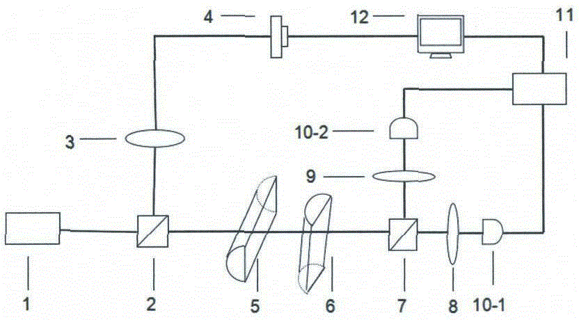
[0033] see figure 1 As shown, it is a schematic structural diagram of a partially coherent Laguerre-Gaussian beam vortex direction measurement device provided in this embodiment: it includes a Laguerre-Gaussian correlated partially coherent light source 1; a first beam splitter 2; Condenser lens 3; beam analyzer 4; first cylindrical lens 5; second cylindrical lens 6; second beam splitter 7; focusing lenses 8, 9; single photon counters 10-1 and 10-2; Coincidence counter 11; computer 12.

[0034]In this embodiment, the Laguerre-Gaussian correlated partially coherent light source 1 generates a partially coherent Laguerre-Gaussian vortex beam; the beam has a coherent vortex structure, and the ro...


PUM


Abstract

The invention discloses a method for determining the direction of a partially-coherent laguerre-gaussian light beam vortex. A partially-coherent laguerre-gaussian light beam which is to be measured is divided into reference light and pilot light through a spectroscope. The pilot light passes through two cylindrical surface lenses which are perpendicular to each other, and transmits for a distance z, and then asymmetric spatial distribution of pilot light intersecting spectral concentration of the pilot light is measured through an association system; the reference light goes through a light beam analysis system so as to measure light intensity spatial distribution of the light beam; the asymmetric spatial distribution of pilot light intersecting spectral concentration which is measured above and the light intensity spatial distribution of the reference light are subjected to computer processing according to first-order coherence degree vortex distribution characteristics of the laguerre-gaussian light beam to obtain a first-order coherence degree distribution map of the to-be-measured light beam. The deflection direction of a symmetric axis of the distribution map is corresponding to the direction of the partially-coherent laguerre-gaussian light beam vortex. The method provided by the invention for measuring the direction of the light beam coherent vortex does not require expensive apparatuses. The measurement apparatus is simple. The determination is visual. The result is reliable.

Description

technical field [0001] The patent of the present invention provides a method for judging the vortex direction of a partially coherent Laguerre-Gaussian beam. The method can be applied to a partially coherent vortex optical system with low coherence, and belongs to the field of partially coherent optical measurement. Background technique [0002] Optical vortices appear as singular points in light fields. At this position, the amplitude of the light field is zero and the phase cannot be defined. Near the singular point of the light field, the isophase surface presents a spiral distribution. This helical phase distribution makes the optical vortex-carrying optical vortex beams have orbital angular momentum, and thus shows great application prospects in many nearby fields such as optical trapping, atomic manipulation, information storage, and quantum communication. The research on optical vortex develops rapidly and becomes an important branch of modern optics. [0003] In ...

Claims


Application Information

Patent Timeline
Patent Type & Authority Applications(China)
IPC IPC(8): G01J11/00
Inventor 陈君陈香云
Owner CHINA JILIANG UNIV
Learn More