Tube drawing mold

A mold and mold core technology, which is applied in the field of molds for drawing metal pipes, can solve the problems of inability to correct the wall thickness difference of the blank pipe, small deformation at the wall thickness, energy and time consumption, etc., to save energy and time , improve the smoothness and reduce consumption

Inactive Publication Date: 2016-01-20
HENGYANG HONGYUAN PIPE IND CO LTD
View PDF9 Cites 1 Cited by
  • Summary
  • Abstract
  • Description
  • Claims
  • Application Information

AI Technical Summary

Problems solved by technology

The deficiencies of the prior art are: 1. Equal-diameter wall-reducing tube extraction relies on the deformation of the inner wall of the steel pipe to correct the wall thickness. If the wall thickness difference of the blank tube is large, the deformation of the thin wall will be large during drawing. The deformation of the wall thickness is small, which cannot effectively correct the wall thickness difference of the blank tube, and will even increase the wall thickness difference
2. For non-equal-diameter wall-reducing tube extraction, the difference between the outer diameter of the rough tube and the outer diameter of the finished tube should not be too large. The ratio of the outer diameter of the rough tube to the outer diameter of the finished tube is 1.06:1. For example, the outer diameter of the finished tube is 100mm, and the rough tube used The maximum outer diameter of the tube is 106mm. If the outer diameter of the rough tube is 110mm, it will be drawn twice. The first time the rough tube with an outer diameter of 110mm is drawn into a tube with an outer diameter of 106mm, and then the tube with an outer diameter of 106mm is pulled out. Drawing into a finished tube with an outer diameter of 100mm, pulling out the tube twice consumes energy and time twice, which consumes a lot of energy and is inefficient

Method used


Image

  • Tube drawing mold
  • Tube drawing mold
  • Tube drawing mold

Examples


Embodiment Construction

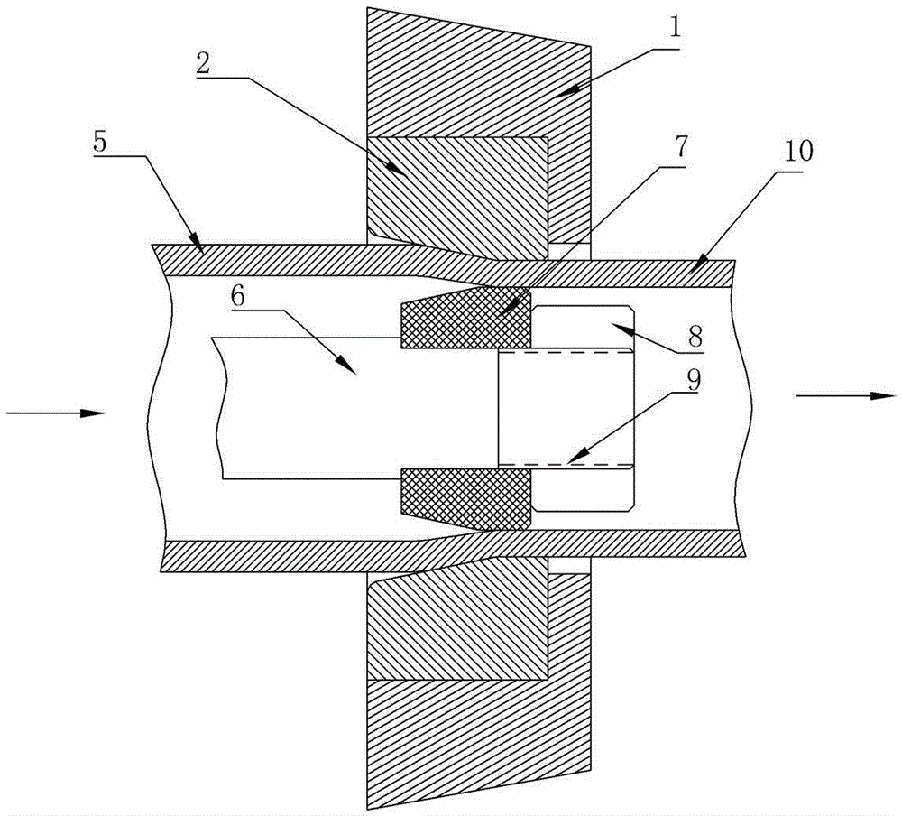
[0017] see figure 1 , is a schematic diagram of the installation relationship of the outer mold, the inner mold, and the steel pipe of the extubation mold of the present invention, and indicates the extubation direction. The outer mold includes a mold sleeve 1 and a mold core 2, the mold core is installed in the mold sleeve, and the mold sleeve is installed in the mold seat of the tube pulling machine. Inner mold 7 is installed on the inner mold mandrel 6, and locking nut 8 is screwed into the screw thread 9 of mandrel front end, and inner mold is positioned. The mandrel is installed on the extubation machine. figure 1 It also shows the change of the steel pipe before and after the mold. The left side of the mold is the blank pipe 5, and the right side is the finished pipe 10. The arrow in the figure indicates the drawing direction, that is, the forward direction of the finished pipe.

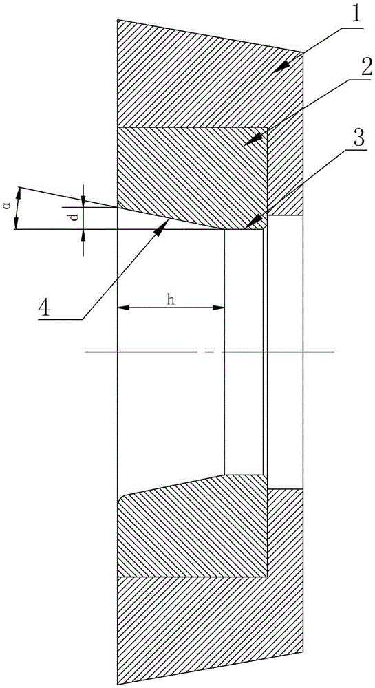
[0018] see figure 2 , is the first embodiment of the outer mold structure of the presen...


PUM


Abstract

The invention discloses a tube drawing mold. The tube drawing mold comprises an outer mold body and an inner mold body. The outer mold body comprises a mold sleeve and a mold core, the mold core is installed in the mold sleeve, and the mold sleeve is installed in a mold base of a tube drawing machine. An inner hole of the mold core comprises a horn opening section and a sizing belt section for determining the outer diameter of a finished tube. An angle a of the horn opening section is calculated according to the outer diameter of a blank tube, the outer diameter of the finished tube and the height of the horn opening section, and the computational formula is tan a=d/h, wherein d is a half of the value obtained by subtracting the outer diameter of the finished tube from the outer diameter of the blank tube, h is the height of the horn opening section, and the angle a can be changed within the range from -2 degrees to 4 degrees. The mold core is composed of a core body and a core, the core body is installed in the mold sleeve, and the core is installed in the core body. When the steel tube is drawn through the tube drawing mold, the tube drawing mold has the beneficial effects that the product quality can be improved, the product yield can be increased, energy, time and cost can be saved, and the cost can be reduced.

Description

technical field [0001] The invention relates to a mold for drawing metal pipes, especially a mold for drawing steel pipes. Background technique [0002] The extubation mentioned in this document refers to the drawing of steel pipes, and the rough pipes are drawn into finished pipes with a pipe extubation machine and molds. The mold for drawing steel pipes in the prior art includes an outer mold and an inner mold. The outer mold includes a mold sleeve and a mold core. The mold core is installed in the mold sleeve. The angle а is constant, that is, regardless of the size of the outer diameter of the blank tube, the angle а is the same. There are two cases of drawing steel pipes in the prior art. The first is equal-diameter wall-reducing pipe drawing, that is, the outer diameters of the rough pipe and the finished pipe are equal, just to correct the wall thickness so that the wall thickness meets the design requirements of the finished pipe. The second is non-equal-diameter w...

Claims


Application Information

Patent Timeline
Patent Type & Authority Applications(China)
IPC IPC(8): B21C3/02B21C3/16
CPCB21C3/02B21C3/16
Inventor 魏守方
Owner HENGYANG HONGYUAN PIPE IND CO LTD
Why Eureka
Try Eureka