


Quick Research
Generate reliable direction feasibility study reports for your R&D in just a few steps.

Technical Q&A
Discover and master advanced knowledge NOW. Basics, ideas, possibilities, all at once.

Find Solutions
As an expert in R&D theories, this can generate solutions to your technical problems instantly.

Evaluate Feasibility
Analyze your overall solution with one click, know your potential R&D risks in advance.

Monitor Landscape
Get weekly tech updates, stay abreast of the latest tech innovations and key insights.
Frequency-response function measurement method employing pulse-like excitation
A technology of pulse excitation and frequency response function, which can be used in measurement devices, testing of machine/structural components, vibration testing, etc., and can solve problems such as frequency confusion.
- Summary
- Abstract
- Description
- Claims
- Application Information
AI Technical Summary
Problems solved by technology
Method used
Image


Examples
Embodiment 1
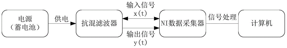
[0081] The measuring system that embodiment 1 adopts is as figure 2 As shown, the measurement system is composed of conventional equipment, including NI data collectors, power supplies, anti-aliasing filters, computers, etc. Use a computer to make a pulse-like excitation signal, which is input to the anti-aliasing filter through the NI data collector, and at the same time use the data collector to collect the input signal x(t) and output signal y(t) of the anti-aliasing filter, In the computer, the signal processing of the input and output signals of the anti-aliasing filter and the calculation of the frequency response function are programmed according to the method of the present invention.
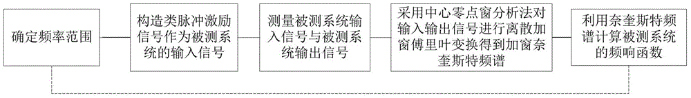
[0082] The specific measurement process of embodiment 1 is as figure 1 As shown, the specific steps are as follows:
[0083] 1) Determine the frequency range of the system under test:
[0084] In embodiment 1, the frequency range is [10Hz, 1500Hz]
[0085] 2) Design pulse excitation ...
Embodiment 2
[0110] The measuring system that embodiment 2 adopts is as Figure 4 As shown, the measurement system is composed of conventional equipment, including NI data collectors, acceleration sensors, piezoelectric ceramic strain gauges, power supplies, cantilever beams, computers, etc. Use the computer to make a pulse-like excitation signal, and input it into the piezoelectric ceramic strain gauge through the NI data collector. The strain gauge provides a pulse-like excitation to the cantilever beam at the fixed end of the cantilever beam. The acceleration sensor is installed at the cantilever end of the cantilever beam. The data collector collects the input signal x(t) of the fixed end and the output signal y(t) of the cantilever end, and performs signal processing of the input signal and output signal and calculation of the system frequency response function by programming in the computer according to the method of the present invention.
[0111] The specific measurement process of...
PUM
| Property | Measurement | Unit |
|---|---|---|
| Resonance frequency | aaaaa | aaaaa |
Abstract
Description
Claims
Application Information
 - R&D Engineer
- R&D Manager
- IP Professional
- Industry Leading Data Capabilities
- Powerful AI technology
- Patent DNA Extraction
Browse by: Latest US Patents, China's latest patents, Technical Efficacy Thesaurus, Application Domain, Technology Topic, Popular Technical Reports.
© 2024 PatSnap. All rights reserved.Legal|Privacy policy|Modern Slavery Act Transparency Statement|Sitemap|About US| Contact US: help@patsnap.com