
Precise shooting calibration device of small arms

A technology for precise shooting and calibrating devices, which is applied in the direction of weapon accessories, offensive equipment, and gun fixing, etc. stuck effect

Active Publication Date: 2016-01-13
FUJIAN LONGXI BEARING (GROUP) CO LTD +1
View PDF8 Cites 10 Cited by
  • Summary
  • Abstract
  • Description
  • Claims
  • Application Information

AI Technical Summary

Problems solved by technology

The calibration method of firing 4 rounds by a so-called excellent shooter to find the average impact point has the following disadvantages: large human interference, low calibration accuracy, low work efficiency, and the gun calibration relies heavily on the so-called excellent shooter
[0008] The Chinese Utility Model Patent No. ZL200520000981.6 discloses a universal calibrator for guns used by military and police squads, which has obvious shortcomings: a rigid connection is adopted between the firearm and the calibrator, and the recoil force during shooting will produce a turning moment; The patent fails to effectively eliminate the overturning moment generated by the recoil of the firearm, causing at least two adverse consequences: one is to reduce the shooting accuracy, which in turn affects the calibration accuracy, and the other is to easily damage the parts of the calibrator
At the same time, the patent has obvious imprecise expressions, such as: "realize the four-axis coaxiality of the central axis of the barrel, the mechanical aiming baseline, the optical aiming axis, and the electronic aiming axis", because the above four axes are straight lines that are not on the same plane. possibly coaxial, therefore, the patent's perception of the nature of the calibration is biased

Method used


Image

  • Precise shooting calibration device of small arms
  • Precise shooting calibration device of small arms
  • Precise shooting calibration device of small arms

Examples


Embodiment Construction

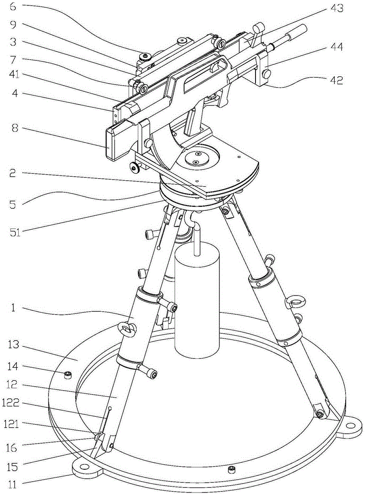
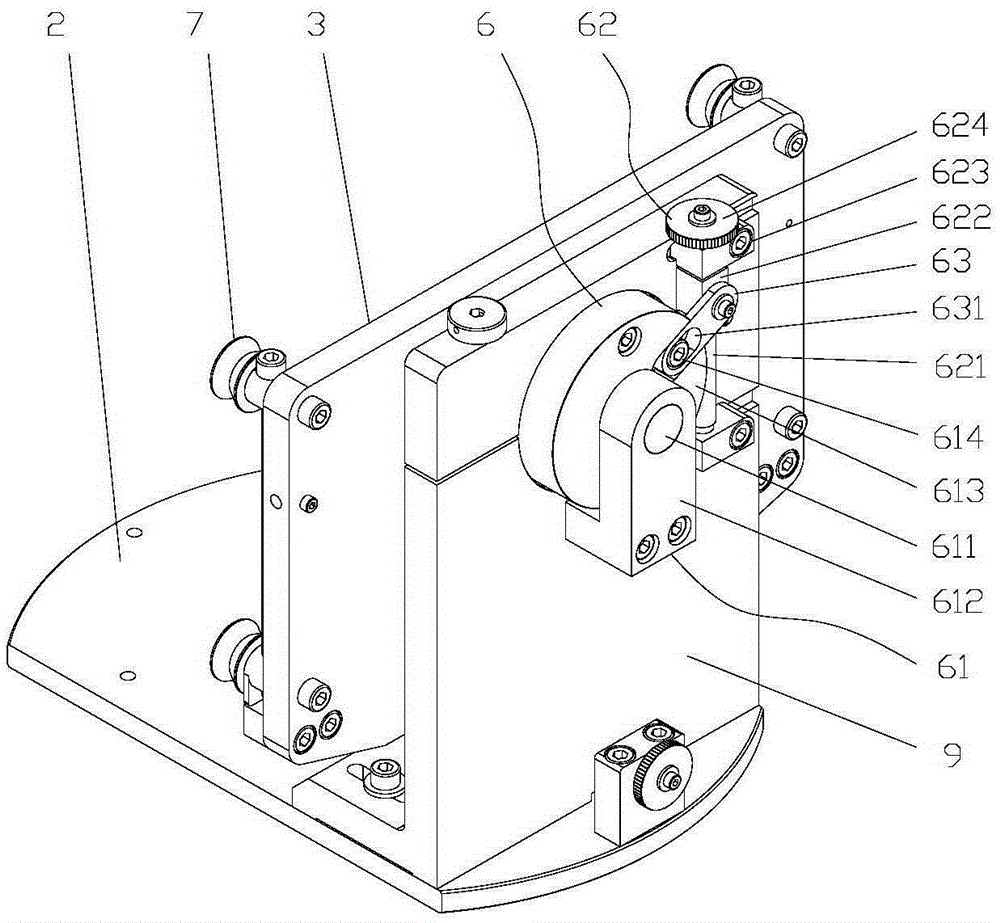
[0036] Such as Figure 1-5 As shown in one of them, the present invention comprises a support 1, a horizontal plate 2, a track vertical plate 3, a base 9 and a stock plate 4 for clamping a light weapon 8, and the horizontal plate 4 is horizontally arranged on the support by a horizontal adjustment mechanism 5. 1, the base 9 is vertically arranged on the horizontal plate 2, the other side of the track riser 3 is rotatably connected to the base 9 through a pitch adjustment mechanism 6, and one side of the track riser 3 is provided with adjustable track spacing The track device 7, the butt plate 4 is slidably arranged on the track device 7.

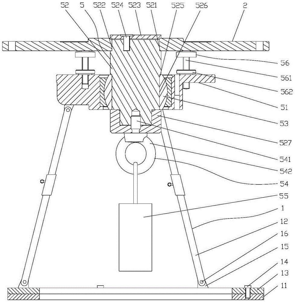
[0037] Such as figure 2 As shown, the horizontal adjustment mechanism 5 includes a mounting base 51 and a vertical shaft 52, the mounting base 51 is arranged on the bracket 1, the mounting base 51 is provided with a joint bearing 53, and the lower part of the vertical shaft 52 is fixed on the In the joint bearing 53, a connecting piece 54...


PUM


Abstract

The invention relate to the technical field of calibration devices, in particular to a precise shooting calibration device of small arms. The device comprises a bracket, a horizontal disc, a rail vertical plate, a base and a gun support plate for clamping the small arms, wherein the horizontal disc is horizontally arranged on the bracket through a horizontal adjusting mechanism; the base is vertically arranged on the horizontal disc; the other side surface of the rail vertical plate is rotationally connected with the base through a pitching adjusting mechanism; a rail gap adjustable rail device is arranged on one side surface of the rail vertical plate; and the gun support plate is slidingly arranged on the rail device. The device reduces radial runout of the arms, reduces the damage of recoil to the device, eliminates the influence of the recoil process on the shooting precision, realizes precise solution of average impact point only through aiming, performs precise calibration to eliminate the dependence of the arms calibration on excellent shooters, improves the calibration precision, reduces the labor intensity of calibration work, and promotes the calibration efficiency.

Description

technical field [0001] The invention relates to the technical field of calibration devices, in particular to a precision shooting calibration device for light weapons. Background technique [0002] Before shooting live ammunition, the light weapons used must be calibrated; for a good light weapon (rifle, mobile phone, sniper rifle, light machine gun, etc.), the relationship between the average trajectory of the bullet, the axis of the bore, and the line of sight is relatively fixed. [0003] The so-called average trajectory refers to the average trajectory of the bullet after multiple shots under standard meteorological conditions. Its manifestation is often a point on the target at a certain distance from the gun. Taking the Type 95 automatic rifle as an example, its average trajectory is represented as a point on the target 100 meters away from the gun, which is called the average impact point. The reason why it is the average impact point is that even if the gun is stri...

Claims


Application Information

Patent Timeline
IPC IPC(8): F41A27/30F41A27/06
Inventor 蔡士源卢同心陈德平陈志雄颜杨丰叶民强施政中
Owner FUJIAN LONGXI BEARING (GROUP) CO LTD
Learn More