
Sliding door drive device and air conditioning device

A technology for driving devices and sliding doors, which is applied in the direction of heating and ventilation hoods/covers, etc. It can solve the problems that the sliding doors cannot be manually pushed down, the lower panel cannot be removed smoothly, and after-sales work cannot be carried out.

Active Publication Date: 2016-01-13
GREE ELECTRIC APPLIANCES INC
View PDF7 Cites 3 Cited by
  • Summary
  • Abstract
  • Description
  • Claims
  • Application Information

AI Technical Summary

Problems solved by technology

However, due to the self-locking effect of the worm gear drive, the sliding door cannot be pushed manually, resulting in the sliding door cannot be manually pushed down when the sliding door drive mechanism is powered off.
[0005] Especially in after-sales maintenance, the lower panel needs to be disassembled for maintenance. However, when the air conditioning device breaks down and the power is cut off, the sliding door cannot be manually pushed down, so that the lower panel cannot be removed smoothly, which brings great inconvenience to the maintenance. Due to great difficulties, the after-sales work cannot be carried out, and the whole machine can only be returned to the factory for repair

Method used


Image

  • Sliding door drive device and air conditioning device
  • Sliding door drive device and air conditioning device
  • Sliding door drive device and air conditioning device

Examples


Embodiment Construction

[0026] Various embodiments of the invention will be described in more detail below with reference to the accompanying drawings. In the various drawings, the same elements are denoted by the same or similar reference numerals. For the sake of clarity, various parts in the drawings have not been drawn to scale.

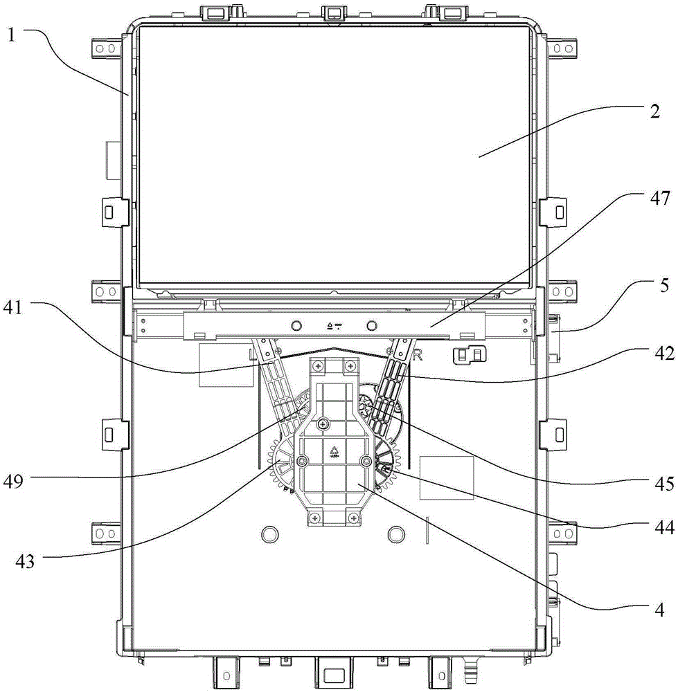
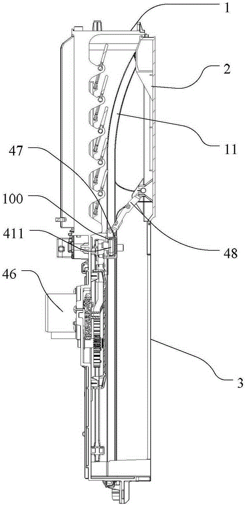
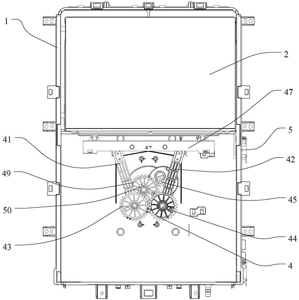
[0027] Such as Figure 1-2 As shown, the air-conditioning device in the present invention includes a mounting bracket 1 located in the device housing, a sliding door 2 slidably arranged on the mounting bracket 1, and a lower panel 3 arranged below the sliding door 2. Both the sliding door 2 and the lower panel 3 are located on the front of the air conditioning device, the sliding door 2 is arranged on the outside of the air outlet of the air conditioning device, and its upper side along the two sides in the width direction is respectively engaged by sliders In the chute 11 arranged on both sides of the inner wall of the installation bracket 1, the sliding door 2 is us...


PUM


Abstract

The invention relates to a sliding door drive device used for driving a sliding door to vertically move. The sliding door drive device comprises a first oscillating bar, a second oscillating bar and a driving wheel. The first oscillating bar and the second oscillating bar are symmetrically arranged. A first driven gear and a second driven gear engaged with the first driven gear are arranged at the lower end of the first oscillating bar and the lower end of the second oscillating bar respectively. The second end of the first oscillating bar and the second end of the second oscillating bar are connected with the sliding door. The driving gear is connected with a power mechanism to drive the first driven gear and the second driven gear to synchronously rotate. In the sliding door drive device, due to the fact that the driven gears for driving the oscillating bars are in gear transmission with the driving gear, the driving gear can be driven by the driven gears for reverse transmission under the action that external force is artificially exerted on the driven gears. When the sliding door drive device cannot be started normally, the sliding door can be manually pushed downwards to the inner side of an air conditioning device, and therefore a lower panel is demounted down, and the air conditioning device is maintained.

Description

technical field [0001] The invention relates to air conditioning technology, in particular to a sliding door driving device and an air conditioning device. Background technique [0002] A slidable sliding door is usually arranged at the air outlet of the current air conditioning device cabinet machine, which is used to close the air outlet when the air conditioning device is in a closed state, and protect the air conditioning device to prevent external dust from passing through. The air outlet enters the inside of the air conditioning device, and the sliding door can move up and down driven by the driving device. [0003] Patent No. CN201010532770.2 discloses a sliding door and a driving structure for the sliding door. The sliding door is arranged on an upper panel, and a lower panel is arranged on the lower side of the upper panel. The sliding door driving device adopts a worm gear transmission mode, but because the helix angle of the worm is smaller than the friction angl...

Claims


Application Information

Patent Timeline
Patent Type & Authority Applications(China)
IPC IPC(8): F24F13/20
CPCF24F13/20
Inventor 臧允舒林裕亮曾辉张永成金海元丘晓宏孟宪运
Owner GREE ELECTRIC APPLIANCES INC
Learn More