A flange structure suitable for infrared thermal imaging module

An infrared thermal imaging, flange technology, applied in installation, optics, instruments, etc., can solve the problems of waste of resources, no versatility, long processing cycle, etc., to avoid excessive rotation, wide application range, and fast combination effect.

Active Publication Date: 2017-11-10
IRAY TECH CO LTD
View PDF4 Cites 0 Cited by
  • Summary
  • Abstract
  • Description
  • Claims
  • Application Information

AI Technical Summary

Problems solved by technology

[0003] Existing flanges need to be customized according to the size of the movement and lens. The processing cycle is long, the cost is high, and there is no versatility. Due to the customization characteristics of infrared, there are many types of movements and lenses, and the flanges are also different.
In the process of R&D, production, and demonstration of infrared thermal imaging cameras, there are a large number of occasions that only need simple imaging. Designing and processing flanges according to the existing method not only takes a long time, but also wastes a lot of manpower and financial resources, resulting in a waste of resources.

Method used


Image

  • A flange structure suitable for infrared thermal imaging module
  • A flange structure suitable for infrared thermal imaging module
  • A flange structure suitable for infrared thermal imaging module

Examples


Embodiment Construction

[0026] The principles and features of the present invention are described below in conjunction with the accompanying drawings, and the examples given are only used to explain the present invention, and are not intended to limit the scope of the present invention.

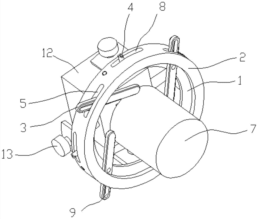
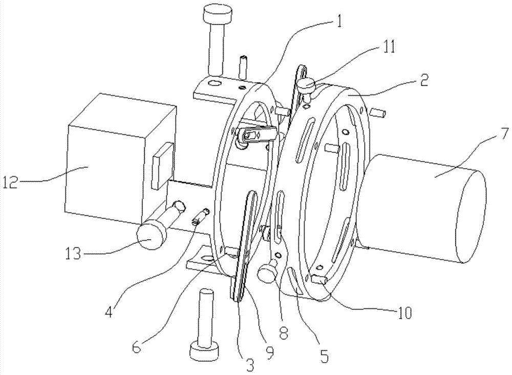
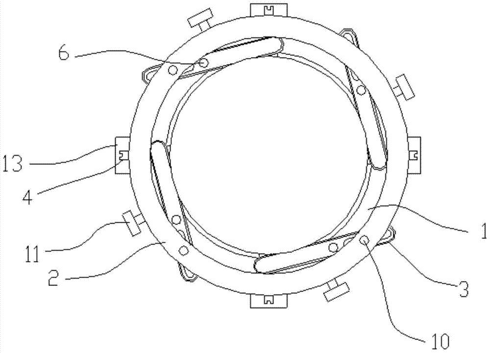
[0027] Such as Figure 1 to Figure 4 As shown, a flange structure suitable for infrared thermal imaging modules includes a core frame 1, a flange ring 2 and claws 3, and the core frame 1 is placed on one side of the flange ring 2, so The core frame 1 is connected with the flange ring 2 through a limit guide nail 4, and the limit guide pin 4 can limit the rotation angle of the flange ring 2 relative to the core frame 1; the flange The ring 2 is provided with a strip-shaped hollow first groove body 5, the claw 3 is placed in the first groove body 5, and the middle part of the claw 3 is rotatably connected with the machine through the rotating shaft 6. The core frame 1 is connected, one end of the claw 3 can touch the...


PUM


Abstract

The invention relates to a flange structure suitable for an infrared thermal imaging module, comprising a core frame, a flange ring and claws, the core frame is placed on one side of the flange ring, and the core frame and The flange ring is connected by a limit guide pin, and the limit guide pin can limit the rotation angle of the flange ring relative to the core frame; the flange ring is provided with a strip-shaped hollow first A tank body, the claw is placed in the first tank body, the middle part of the claw is rotatably connected to the core frame through a rotating shaft, and one end of the claw can touch the flange ring The lens inside, the other end of the claw can touch the edge of the first groove. Compared with the prior art, the present invention is applicable to various combinations of movement and lens, has wide application range, low cost, fast combination speed, and improves the imaging effect of movement and lens.

Description

technical field [0001] The invention relates to a flange structure suitable for an infrared thermal imaging module. Background technique [0002] In recent years, infrared thermal imaging technology has developed rapidly, and there are more and more research and development companies for movement and lens. However, due to the particularity of the industry, the products have not yet been mass-produced, so there is no uniform standard in the industry, resulting in the shape of the movement, The size is different, and the back distance of each lens is inconsistent with the threaded interface; resulting in the problem that the flange is not suitable and cannot be imaged when the lens movement needs to be assembled for imaging in many occasions. At present, there is no good solution, and it can only take time to redesign and process the flange. [0003] Existing flanges need to be customized according to the size of the movement and lens. The processing cycle is long, the cost i...

Claims


Application Information

Patent Timeline
Patent Type & Authority Patents(China)
IPC IPC(8): G02B7/00
CPCG02B7/00
Inventor 孙同波黄星明
Owner IRAY TECH CO LTD
Why Eureka
Try Eureka