
Liquid chromatograph with plunger structure

A liquid chromatograph and plunger technology, which is applied in the field of liquid chromatograph, can solve problems such as unfavorable maintenance, cumbersome operation steps, and reduced service life of the plunger assembly 231, so as to prolong the service life, reduce processing errors and assembly The effect of error, replacement and maintenance is convenient and quick

Active Publication Date: 2016-01-06
达耐科学有限公司
View PDF7 Cites 3 Cited by
  • Summary
  • Abstract
  • Description
  • Claims
  • Application Information

AI Technical Summary

Problems solved by technology

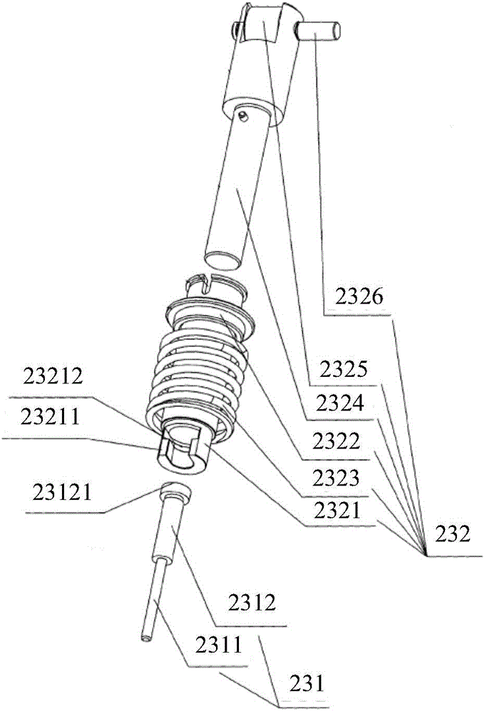
[0005] The above structure has the following problems: when the plunger assembly 231 is worn and needs to be replaced, or the plunger assembly 231 needs to be maintained due to leakage of the sealing ring in the pump head cavity, it is necessary to remove other parts on the upper part of the high-pressure infusion pump, and open the upper part of the high-pressure infusion pump. machine cover, and use tools to loosen the spring 2323 acting on the split piston rod, and the plunger assembly 231 can only be taken out after the pump head assembly is removed. This operation is cumbersome and very unfavorable for maintenance
In addition, this plunger structure is in a fixed state after assembly. Although the plunger assembly 231 can be kept coaxial with each sealing assembly of the pump head assembly during assembly, it cannot be real-time during the reciprocating movement of the plunger assembly 231. The self-adaptation makes the plunger assembly 231 eccentrically wear the sealing ring, reducing the service life of the plunger assembly 231

Method used


Image

  • Liquid chromatograph with plunger structure
  • Liquid chromatograph with plunger structure
  • Liquid chromatograph with plunger structure

Examples


Embodiment Construction

[0031] In order to make the above objects, features and advantages of the present invention more comprehensible, the present invention will be further described in detail below in conjunction with the accompanying drawings and specific embodiments.

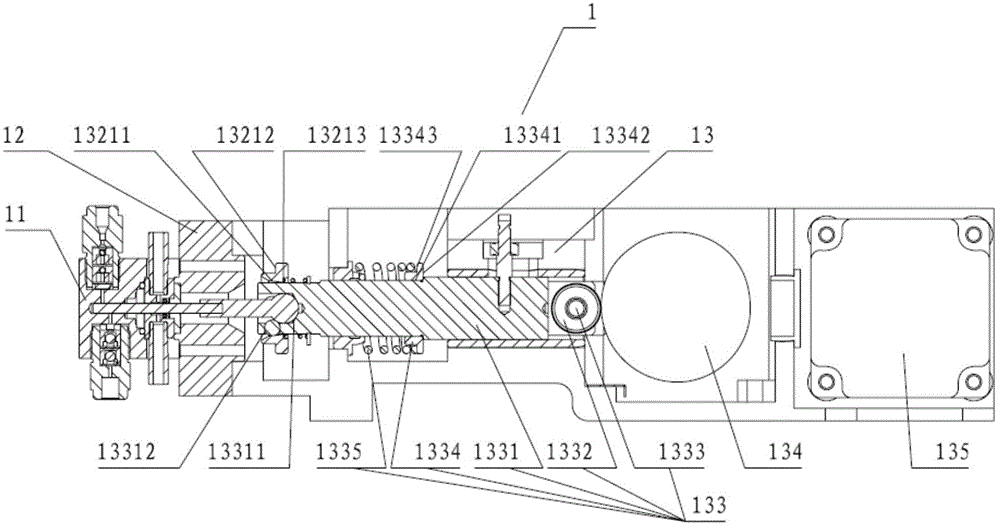
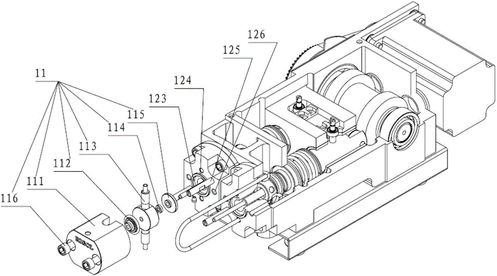
[0032] An embodiment of the present invention provides a liquid chromatograph with a plunger structure, and the liquid chromatograph includes a high-pressure infusion pump. refer to figure 2 , shows a schematic structural diagram of a high-pressure infusion pump 1 provided by an embodiment of the present invention. combine image 3 with Figure 4, the high-pressure infusion pump 1 includes two pump head assemblies 11, two pump head seats 12 connected to the pump head assemblies 11 and a pump body 13 connected to the two pump head seats 12; the pump body 13 includes two plunger assemblies 131 , two piston assemblies 133, a cam assembly 134 and a motor 135; one end of the plunger assembly 131 is passed through the pump head asse...


PUM


Abstract

The invention provides a liquid chromatograph with a plunger structure. The liquid chromatograph comprises a high pressure liquid pump. The high pressure liquid pump comprises two pump head components, two pump head seats, and one pump body. The pump body comprises two plunger components and two piston components with a piston rod. One end of the piston rod is provided with a taper hole. One end of the plunger component has a spherical surface and can be detachably installed in the taper hole. The sidewall of the taper hole is provided a plurality of positioning holes. Multiple positioning beads are embedded into the plurality of positioning holes. One end, which is provided with the taper hole, of the piston rod is sleeved by an elastic locking mechanism, the inner wall of the elastic locking mechanism presses the positioning beads, and the positioning beads press the spherical surface onto the taper bottom surface of the taper hole. The pump head seat is provided with at least two through holes. When the elastic locking mechanism is pushed and pressed through the through holes, the inner wall of the elastic locking mechanism is separated from the positioning beads. The plunger component can be simply and conveniently assembled and disassembled, at the same time, the realtime self-adaption of the plunger component can be achieved during the reciprocated movement, moreover, the wear is reduced, and the service life of the plunger component is prolonged therefore.

Description

technical field [0001] The invention relates to the technical field of test and measurement, in particular to a liquid chromatograph with a plunger structure. Background technique [0002] A liquid chromatograph generally consists of a high-pressure infusion pump, a liquid storage bottle, a sample injector, a chromatographic column, a detector, a waste liquid tank, and a data recording and processing device. One end of the high-pressure infusion pump is connected to the liquid storage bottle through a catheter, the other end is connected to the inlet of the sampler through a catheter, the outlet of the sampler is connected to the inlet of the chromatographic column through a catheter, and the outlet of the chromatographic column is connected to the detector through a catheter. The device is connected with the data recording and processing device through the data line. The working principle of the liquid chromatograph is: the mobile phase is installed in the liquid storage b...

Claims


Application Information

Patent Timeline
IPC IPC(8): G01N30/22
Inventor 罗阁王悦王铁军李维森
Owner 达耐科学有限公司
Learn More