Eureka AIR delivers breakthrough ideas for toughest innovation challenges, trusted by R&D personnel around the world.

Pipeline connector structure convenient to replace and maintain

A technology for pipe joints and joints, which is applied in the direction of pipes/pipe joints/fittings, threaded connections, pipe components, etc. It can solve the problems of easy blockage and cleaning of pipes, low work efficiency, single function, etc., and achieves easy replacement and maintenance. Easy maintenance, good sealing effect

Inactive Publication Date: 2018-09-18
JIANGSU PEIDA PLASTIC
View PDF6 Cites 2 Cited by
  • Summary
  • Abstract
  • Description
  • Claims
  • Application Information

AI Technical Summary

Problems solved by technology

[0002] With the rapid development of the economy, the shortage of metal resources is becoming more and more serious. Plastics are widely used and have gradually replaced metals in many places, playing a huge role, especially in the laying and connection of pipelines and pipeline installation. In the process, connectors are often needed to connect, but the current pipe connectors are basically fixed by the two ends and the external connecting pipe threads. The structure is relatively simple and the function is single. At present, the following problems exist in the design of plastic pipe connectors: After the pipeline is connected with the connector, it is time-consuming and labor-intensive to fix it separately with fasteners; second, the inner cavity of the pipeline connector has no filtering device, and the pipeline is easy to block and inconvenient to clean; third, when the pipeline leaks and repairs, the main valve needs to be closed, No current limiting device is installed, maintenance is inconvenient, and work efficiency is low. Therefore, further improvement and perfection are needed

Method used

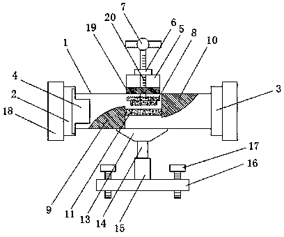
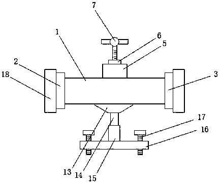

Image

  • Pipeline connector structure convenient to replace and maintain
  • Pipeline connector structure convenient to replace and maintain
  • Pipeline connector structure convenient to replace and maintain

Examples


Embodiment Construction

[0017] The preferred embodiments of the present invention will be described below in conjunction with the accompanying drawings. It should be understood that the preferred embodiments described here are only used to illustrate and explain the present invention, and are not intended to limit the present invention.

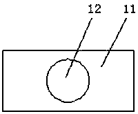
[0018] Such as Figure 1-Figure 3 As shown, a pipe connector structure that is easy to replace and maintain, includes a connector body 1, the two sides of the connector body 1 are respectively provided with a water inlet 2 and a water outlet 3, and the inner cavity of the water inlet 2 is installed with a filter Cover 4, by setting the filter cover 4, impurities in the water can be filtered to prevent the pipeline from being blocked. The top of the connector main body 1 is fixed with a sealing cylinder 5, and the top surface of the sealing cylinder 5 is inlaid with a first fixing nut 6. The first fixing nut 6 is threadedly connected with a T-shaped threaded rod 7, a...


PUM


Abstract

The invention relates to a pipeline connector structure convenient to replace and maintain. The pipeline connector structure comprises a connector body. A water inlet and a water outlet are arranged on the two sides of the connector body correspondingly. A filter cover is mounted in an inner cavity of the water inlet. A sealing barrel is fixedly arranged at the top of the connector body. A first fixed nut is mounted on the surface of the top of the sealing barrel in an embedded manner. The first fixed nut is in threaded connection with a T-shaped threaded rod. Through the arrangement of a second fixed nut, connection and fixing between a pipeline and the connector body are convenient; through the arrangement of a threaded supporting leg and a threaded roller, the distance between a mounting plate and the connector body can be adjusted by rotating the threaded roller, and different mounting requirements can be met; the surface of an upper valve seat and the surface of a lower valve seatare arranged to be of arc structures, and water flow resistance is reduced; and scale lines are drawn on the surface of the front side of the T-shaped threaded rod, the position of a sealing plug canbe judged according to the length values marked on one side of the scale lines, and the water flow speed can be judged.

Description

technical field [0001] The invention relates to a pipe connection head structure which is convenient for replacement and maintenance, and belongs to the technical field of pipe connection heads. Background technique [0002] With the rapid development of the economy, the shortage of metal resources is becoming more and more serious. Plastics are widely used and have gradually replaced metals in many places, playing a huge role, especially in the laying and connection of pipelines and pipeline installation. In the process, connectors are often needed to connect, but the current pipe connectors are basically fixed by the two ends and the external connecting pipe threads. The structure is relatively simple and the function is single. At present, the following problems exist in the design of plastic pipe connectors: After the pipeline is connected with the connector, it is time-consuming and labor-intensive to fix it separately with fasteners; second, the inner cavity of the pip...

Claims


Application Information

Patent Timeline
IPC IPC(8): F16L15/08F16L55/24
CPCF16L15/08F16L55/24
Inventor 缪培峰
Owner JIANGSU PEIDA PLASTIC
Why Eureka
Eureka Blog
Learn More