Air flue air distribution structure of heat pump drying machine

A heat pump drying and air duct technology, applied in progressive dryers, drying gas layouts, dryers, etc., can solve problems such as high cost, high drying efficiency, heat loss, etc., to improve efficiency, reasonable air duct layout, cost reduction effect

Active Publication Date: 2016-01-06
DONGGUAN DONGYUAN ENVIRONMENTAL TECH CO LTD
View PDF10 Cites 1 Cited by
  • Summary
  • Abstract
  • Description
  • Claims
  • Application Information

AI Technical Summary

Problems solved by technology

[0004] In view of this, the present invention aims at the deficiencies in the prior art, and its main purpose is to provide a heat pump dryer air distribution structure, which can effectively solve the problem of high cost, large heat loss and low drying efficiency of existing heat pump drying equipment. The problem

Method used


Image

  • Air flue air distribution structure of heat pump drying machine
  • Air flue air distribution structure of heat pump drying machine

Examples


Embodiment Construction

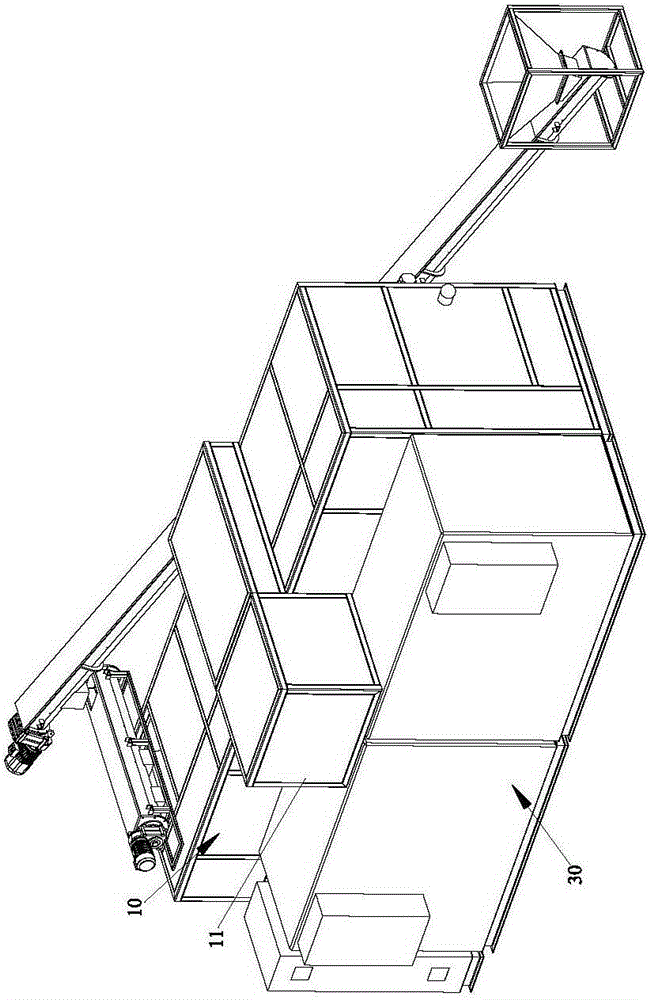
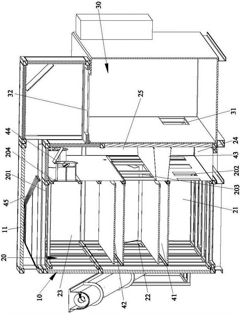
[0027] Please refer to figure 1 and figure 2 As shown, it shows the specific structure of the preferred embodiment of the present invention, including a casing 10 , a drying chamber 20 and a heat pump host 30 .

[0028] The housing 10 is formed by encapsulating the insulation board 11. The drying chamber 20 is arranged in the housing 10. The drying chamber 20 is provided with a lower conveying mesh belt 41 and an upper conveying mesh belt 42. The lower conveying mesh belt 41 is formed with a first Space 21, the second space 22 is formed between the upper conveying mesh belt 42 and the lower conveying mesh belt 41, the third space 23 is formed above the upper conveying mesh belt 42, and the top of the drying chamber 20 is provided with a first tuyere 201 for drying The side of the chamber 20 is provided with a second tuyere 202, a third tuyere 203 and a fourth tuyere 204 in sequence from bottom to top; a windshield 43 is set between the heat pump main unit 30 and the drying c...


PUM


Abstract

The invention discloses an air flue air distribution structure of a heat pump drying machine. The air flue air distribution structure comprises a shell, a drying chamber and a heat pump main engine. The shell is formed by packaging an insulation board. A lower conveying net belt and an upper conveying net belt are arranged in the drying chamber. First space is formed below the lower conveying net belt. Second space is formed between the upper conveying net belt and the lower conveying net belt. Third space is formed above the upper conveying net belt. A first air opening is formed in the top of the drying chamber. Second air openings, third air openings and fourth air openings are formed in the sided face of the drying chamber from bottom to top in sequence. An inner circulation air flue and an outer circulation air flue can be formed, the air flues are arranged reasonably and inlaid in the drying chamber, closed circulation is achieved, full heat preservation is achieved, heat is prevented from being lost, and the cost for manufacturing an outer independent air flue is omitted. In addition, dry air can be fully saturated to take away more water, the drying efficiency is improved, and the problem that sludge on the upper conveying net belt is dried unevenly is solved.

Description

technical field [0001] The invention relates to the technology in the field of dryers, in particular to an air distribution structure for an air duct of a heat pump dryer. Background technique [0002] The Ministry of Housing and Urban-Rural Development predicts that the amount of sludge that needs to be safely treated and disposed of in cities and towns in my country will reach 31.43 million tons in 2015 according to the target requirements for the treatment rate of sewage discharge during the "Twelfth Five-Year Plan" period. In addition, the rivers and lakes adjacent to cities in my country have been seriously polluted, and the sediment containing high concentrations of heavy metals and toxic organic substances urgently needs to be excavated, dredged and treated. [0003] Heat pump drying is a recognized green drying technology. However, at present, heat pump drying equipment needs to manufacture an external separate air duct, which increases the cost, increases the heat l...

Claims


Application Information

Patent Timeline
Patent Type & Authority Applications(China)
IPC IPC(8): F26B21/02F26B15/10F26B23/00
Inventor 肖应东
Owner DONGGUAN DONGYUAN ENVIRONMENTAL TECH CO LTD
Why Eureka
Try Eureka