
Swing vane drive and air conditioner

A driving device and driving component technology, applied in lighting and heating equipment, space heating and ventilation details, heating methods, etc., can solve the driving failure, the deformation of the connecting rod crank 400, the swing angle of the connecting rod crank 400 driving the swing blade 700 Smaller and other problems to achieve the effect of ensuring reliability and effectiveness

Active Publication Date: 2018-11-16
TCL AIR CONDITIONER ZHONGSHAN CO LTD
View PDF5 Cites 0 Cited by
  • Summary
  • Abstract
  • Description
  • Claims
  • Application Information

AI Technical Summary

Problems solved by technology

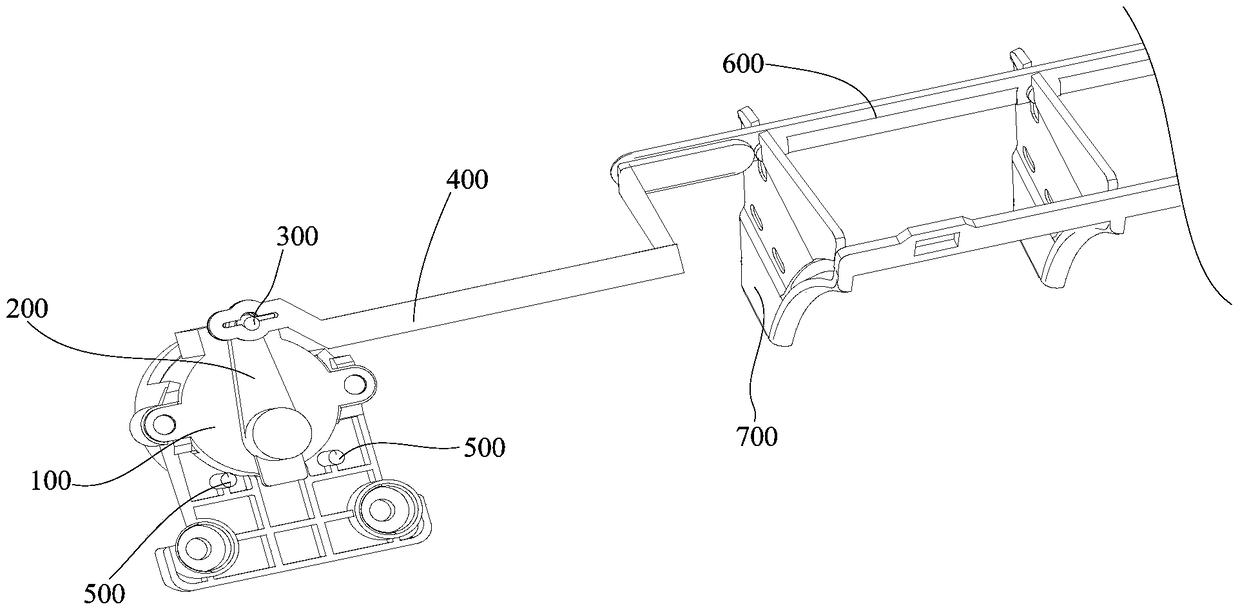
[0003] In the existing pendulum blade drive mode, since the crank 200 is driven by the motor 100, the short pin 300 moves in a circle around the rotating shaft. The trajectory pulls the movement, so that the connecting rod crank 400 is subjected to multiple forces that are not in the same straight line direction. After a long time of use, the connecting rod crank 400 will be deformed, causing the swing angle of the connecting rod crank 400 to drive the swing blade 700 to become smaller, and even drive Failure etc.

Method used

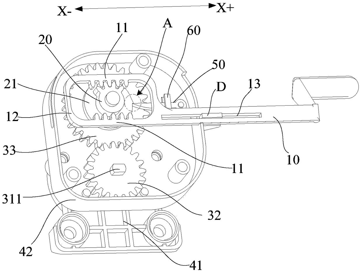
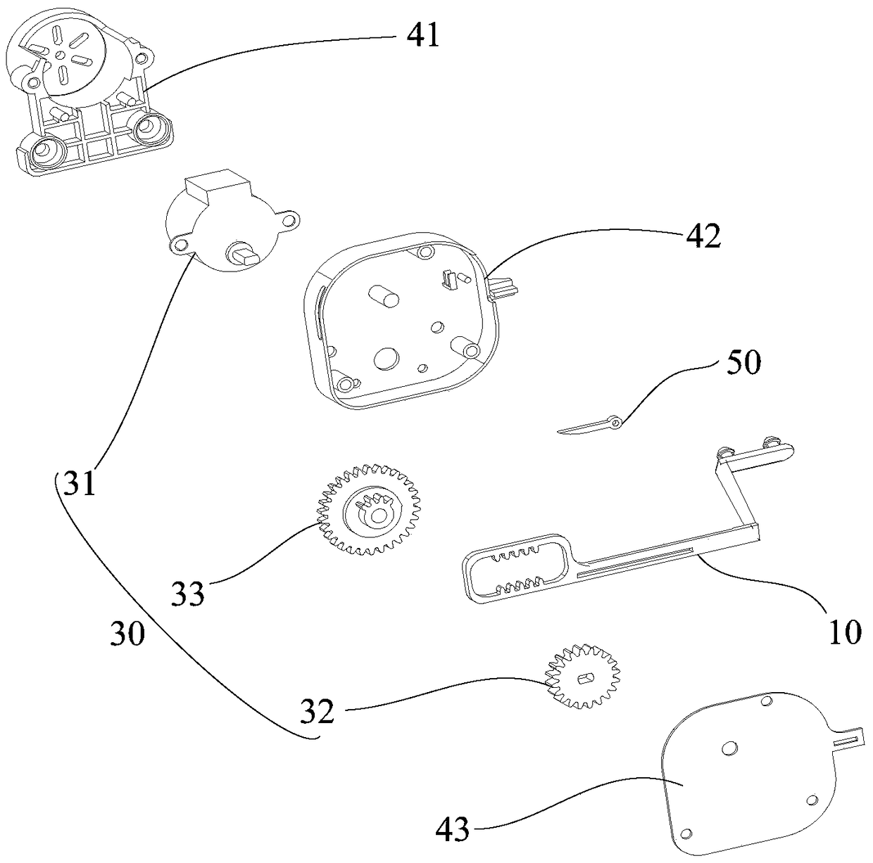

Image

  • Swing vane drive and air conditioner
  • Swing vane drive and air conditioner
  • Swing vane drive and air conditioner

Examples


Embodiment Construction

[0030] The technical solutions of the present invention will be further described below in conjunction with the accompanying drawings and specific embodiments. It should be understood that the specific embodiments described here are only used to explain the present invention, not to limit the present invention.

[0031] The present invention proposes a swing vane driving device, which is applied in an air conditioner and is used for connecting with a connecting rod that drives the swing vane to drive the swinging wind of the swing vane.

[0032] refer to figure 2 and image 3 , in the embodiment of the present invention, the swing blade driving device includes a connecting rod crank 10, a sector gear 20 and a drive assembly 30 for driving the sector gear 20 to rotate. One end of the connecting rod crank 10 is provided with two connecting rod cranks 10 in the length direction (ie figure 2 The X-axis direction in the middle) parallel racks 11, the two racks 11 are arranged ...


PUM


Abstract

The invention discloses a swing vane driving device and an air conditioner. The swing vane driving device comprises a connecting rod crank, a sector gear and a driving component used for driving the sector gear to rotate. Two racks parallel to the length direction of the connecting rod crank are arranged at one end of the connecting rod crank in a spaced mode. The sector gear is arranged between the two racks and engaged with one of the racks. When the driving component drives the sector gear to rotate in the same direction, the sector gear is engaged with the two racks periodically and alternatively so as to drive the connecting rod crank to move back and forth periodically. According to the technical scheme, the condition that the connecting rod crank is bent and deformed due to the fact that a plurality of acting forces which are not in the same straight line act on the connecting rod crank is avoided, and the reliability and effectiveness of the driving of the connecting rod crank are ensured.

Description

technical field [0001] The invention relates to the technical field of air conditioning, in particular to a swing blade driving device and an air conditioner. Background technique [0002] The structure of the swing blade driving device of the existing air conditioner is as follows: figure 1 As shown, the motor 100 is installed on a motor base, the crank 200 is inserted on the rotating shaft of the motor 100, and the rotating shaft of the motor 100 rotates to drive the crank 200 to rotate; there are limit cylinders 500 on both sides of the lower end of the crank 200 to limit the back and forth rotation of the crank 200 There is a short pin 300 at the upper end of the crank 200, and the short pin 300 is inserted into the round hole at the head end of the connecting rod crank 400. When the crank 200 rotates, it drives the connecting rod crank 400 to move back and forth in the horizontal direction; The connecting rod 600 is connected, and the connecting rod 600 drives the swin...

Claims


Application Information

Patent Timeline
Patent Type & Authority Patents(China)
IPC IPC(8): F24F13/14
CPCF24F13/1426F24F2013/1433F24F2013/1446
Inventor 邓利刘泉吴旭波匡纯纯张成麦文浩
Owner TCL AIR CONDITIONER ZHONGSHAN CO LTD
Learn More