Tubular product connecting structure and water dividing and collecting device

A connection structure and water divider technology, applied in the direction of pipes/pipe joints/pipes, pipes, branch pipelines, etc., can solve problems such as leakage and limited sealing effect of sealing rings.

Active Publication Date: 2016-01-06
RIFENG ENTERPRISE FOSHAN CO LTD +2
View PDF6 Cites 2 Cited by
  • Summary
  • Abstract
  • Description
  • Claims
  • Application Information

AI Technical Summary

Problems solved by technology

The traditional method of connecting the manifold to the pipe is generally a press type or a plug-in type. In order to achieve a sealing effect, a sealing ring is set on the core of the manifold, but the sealing effect of the sealing ring is limited and there is leakage. risks of

Method used


Image

  • Tubular product connecting structure and water dividing and collecting device
  • Tubular product connecting structure and water dividing and collecting device
  • Tubular product connecting structure and water dividing and collecting device

Examples


Embodiment Construction

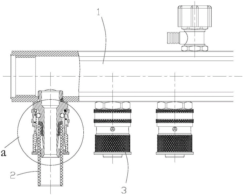
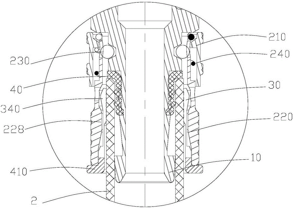
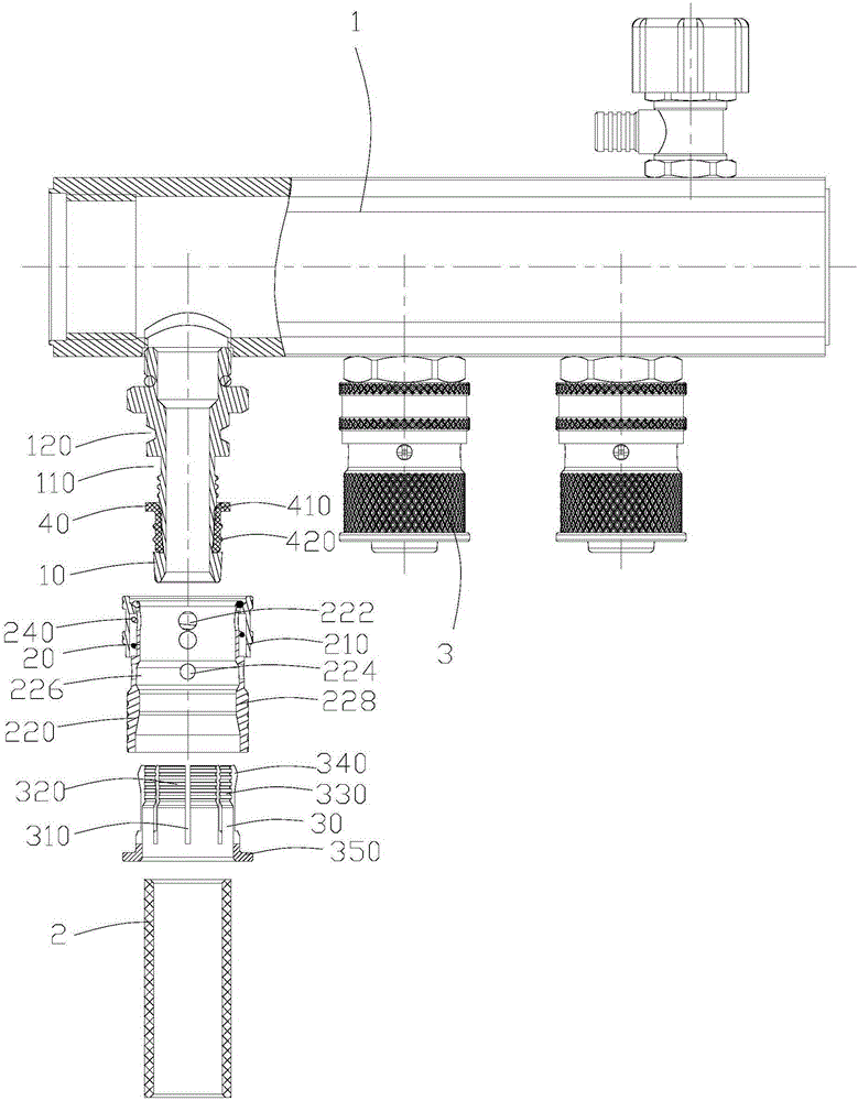
[0026] Such as Figures 1 to 3 As shown, a sub-collector includes a water distributor main pipe 1, a branch pipe 2 and a pipe connection structure 3. The pipe connection structure 3 includes a core body 10, a steel ball circlip mechanism 20, a pipe circlip 30, and a sealing sleeve 40. The outer wall of the core body 10 is provided with an annular groove 110, and the annular groove 110 is arranged at one end close to the outlet of the core body 10, the sealing sleeve 40 is sleeved on the core body 10, and the sealing sleeve 40 is located at In the annular groove 110, the end of the sealing sleeve 40 away from the outlet of the core body 10 is provided with a protrusion 410 protruding in the radial direction thereof, and at least one anti-slip rib 420 is provided on the outer wall of the sealing sleeve 40, and the steel ball retaining spring The mechanism 20 is sleeved on the core body 10 and is detachably connected with the core body 10. The tube retainer 30 is sleeved between ...


PUM


Abstract

The invention relates to a tubular product connecting structure and a water dividing and collecting device. The tubular product connecting structure comprises a core body, a steel ball clamp spring mechanism, a tubular clamp spring and a sealing sleeve. An annular groove is formed in the outer wall of the core body, and is formed in one end close to an outlet of a core body; the sealing sleeve is arranged on the core body in a sleeving manner, and the sealing sleeve is located in the annular groove; a convex blocking body which stretches out in the radial direction of the sealing sleeve is arranged at one end, far away from the outlet of the core body, of the sealing sleeve, and at least one anti-slide rib is arranged on the outer wall of the sealing sleeve; the steel ball clamp spring mechanism is arranged on the core body in a sleeving manner and is detachably connected with the core body; and the tubular clamp spring is arranged between the core body and the steel ball clamp spring mechanism in a sleeved manner. The inner wall of the tubular product is in contact with the outer wall of the sealing sleeve to form radial seal, and the end face of the tubular product abuts against the convex blocking body of the sealing sleeve to form axial seal, so that double seal is achieved between the tubular product and the core body; and the anti-slide ribs are arranged on the outer wall of the sealing sleeve, so that tubular product sliding is avoided, and the further sealing effect is achieved.

Description

technical field [0001] The invention relates to pipe connection technology, in particular to a pipe connection structure and a sub-collector. Background technique [0002] The sub-collector refers to the device used to connect the main heating water supply pipe and the return pipe in the floor heating system, which is divided into two parts: the water separator and the water collector. The water distributor is a water distribution device used to connect the water supply pipes of various heating pipes in the water system, and the water collector is a water collection device used to connect the return pipes of various heating pipes in the water system. The traditional method of connecting the manifold to the pipe is generally a press type or a plug-in type. In order to achieve a sealing effect, a sealing ring is set on the core of the manifold, but the sealing effect of the sealing ring is limited and there is leakage. risks of. Contents of the invention [0003] Based on ...

Claims


Application Information

Patent Timeline
IPC IPC(8): F16L41/03F24D19/10
CPCF16L41/03F24D19/10
Inventor 喻延昭林细勇汪辉罗庆敏姚一杰何旺枝谭学良
Owner RIFENG ENTERPRISE FOSHAN CO LTD
Why Eureka
Try Eureka