
Vehicle positioning method

A vehicle positioning and vehicle technology, applied in the field of vehicle positioning, can solve the problems of increasing the number of base stations required, construction costs, high prices, and vehicle positioning in the correct lane

Active Publication Date: 2015-12-30
武汉客车制造股份有限公司
View PDF8 Cites 47 Cited by
  • Summary
  • Abstract
  • Description
  • Claims
  • Application Information

AI Technical Summary

Problems solved by technology

[0003] The Global Positioning System (GPS) is currently the most widely used vehicle positioning method, and the performance can be improved through the differential method. At present, the positioning accuracy of the Differential Global Positioning System (DGPS) can reach the centimeter level at best, but in complex urban environments, Satellite signals are easily blocked, resulting in poor positioning accuracy or even failure to work, and it is expensive
[0004] Based on the vehicle-to-infrastructure (V2I) positioning method, by analyzing the real-time communication signals between the vehicle and the roadside unit in the Internet of Vehicles, the distance between the roadside unit and the vehicle is measured, and then the vehicle position coordinates are determined through a series of positioning algorithms. Not limited by terrain, it can make up for the lack of GPS, but the positioning process requires the vehicle to communicate with at least three base stations, which greatly increases the number of base stations required and construction costs
[0005] On the other hand, in vehicle positioning, the positioning accuracy requirements along the lateral direction of the road are higher than those required for the longitudinal positioning accuracy. The longitudinal position error can be easily compensated by reserving the longitudinal distance, while the lateral distance of the road is relatively short. If the vehicle is positioned to the wrong The lane will pose a serious threat to driving safety, and the existing positioning methods cannot ensure that the vehicle is positioned on the correct lane

Method used


Image

  • Vehicle positioning method
  • Vehicle positioning method
  • Vehicle positioning method

Examples


Embodiment Construction

[0058] The technical solutions of the present invention will be further described below in conjunction with the accompanying drawings and through specific implementation methods.

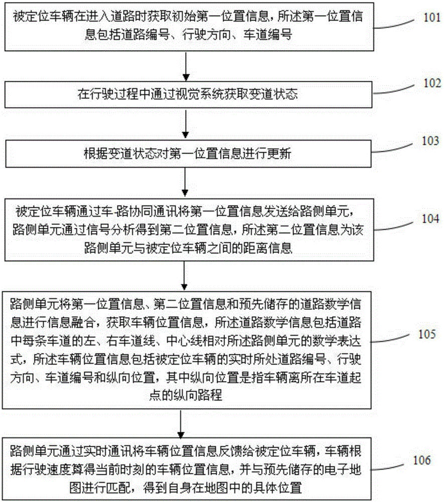
[0059] Such as figure 1 As shown, a kind of vehicle positioning method provided by the present invention, the specific steps are as follows:

[0060] 101: The positioned vehicle acquires initial first location information when entering a road, where the first location information includes road number, driving direction, and lane number;

[0061] Arrange a radio frequency identification tag on the entrance road of each lane of the road that needs to be positioned in advance. The tag contains the road number, driving direction, and lane number. The road number refers to the unique number of the road in the electronic map. number, and the driving direction refers to the direction of vehicles allowed on the side road where the radio frequency tag is located. The lane number indicates which lane the ve...


PUM


Abstract

The invention discloses a vehicle positioning method. The method includes the following steps of obtaining initial first position information when a positioned vehicle enters a road, obtaining a lane change state through a visual system in the driving process, updating the first position information according to the lane change state, sending the first position information to a road side unit by the positioned vehicle through vehicle-road coordinative communication, obtaining second position information through signal analysis by the road side unit, fusing the first position information, the second position information and prestored road mathematic information through the road side unit, obtaining vehicle position information of the positioned vehicle, feeding final position information back to the positioned vehicle through real-time communication by the road side unit, and obtaining the specific position of the vehicle in a map. The vehicle positioning method is not limited by geography, accurate positioning can be completed in the urban environment with unsatisfactory GPS / DGPS accuracy, and the requirements of the intelligent vehicle for collision avoidance, autonomous driving and other application are met.

Description

technical field [0001] The invention relates to the technical field of vehicle positioning, in particular to a vehicle positioning method for joint positioning based on radio frequency identification, vehicle vision and vehicle-road coordination. Background technique [0002] The Internet of Vehicles system is a network and application system that has emerged in recent years with the main purpose of improving traffic efficiency and traffic safety. Vehicle positioning technology is one of the key technologies. Acquiring accurate positions is important for improving the safety of intelligent vehicles and realizing autonomous driving. Significance. [0003] The Global Positioning System (GPS) is currently the most widely used vehicle positioning method, and the performance can be improved through the differential method. At present, the positioning accuracy of the Differential Global Positioning System (DGPS) can reach the centimeter level at best, but in complex urban environm...

Claims


Application Information

Patent Timeline
IPC IPC(8): G08G1/123
Inventor 陈峥曹立波颜凌波秦勤
Owner 武汉客车制造股份有限公司
Learn More