
Squirrel-cage water magnetizing equipment

A magnetized water and squirrel-cage technology, applied in the direction of magnetic field/electric field water/sewage treatment, etc., can solve the problems of hydrogen bond elongation, etc., and achieve the effects of fast structure, high magnetization efficiency and strong magnetism

Active Publication Date: 2015-12-30
SUZHOU UNIV
View PDF8 Cites 2 Cited by
  • Summary
  • Abstract
  • Description
  • Claims
  • Application Information

AI Technical Summary

Problems solved by technology

However, since the directions of the magnetic field lines in the S-shaped circuitous water flow channel in the above-mentioned device are all parallel and in the same direction, the force of the magnetic field lines on the water molecules is in the same direction. The hydrogen bonds of the molecules are elongated, bent or even broken, and the magnetic force of the magnet plate set in the device needs to be very strong to realize that the hydrogen bonds of the associated water molecules are elongated, bent or even broken

Method used


Image

  • Squirrel-cage water magnetizing equipment
  • Squirrel-cage water magnetizing equipment
  • Squirrel-cage water magnetizing equipment

Examples


Embodiment 1

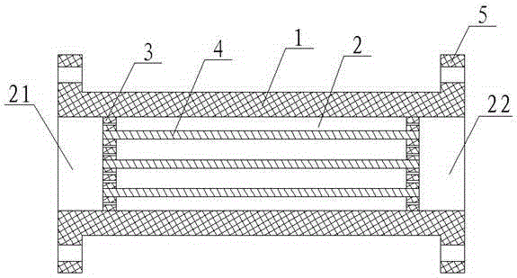
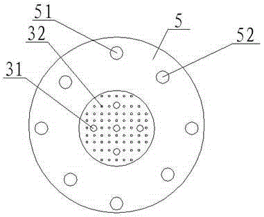
[0026] see figure 1 and figure 2 , as shown in the legend therein, a squirrel-cage magnetized water device includes a housing 1 , a passage 2 passing through the housing 1 and a magnetization system disposed in the passage 2 . One end of the channel 2 is a water inlet 21, and the other end of the channel 2 is a water outlet 22. A bracket assembly is arranged in the channel 2. The bracket assembly includes two partitions 3, and the two partitions 3 are respectively arranged at different longitudinal positions of the channel 2. position, the circumferential surface of the partition 3 is relatively fixed to the inner wall of the channel 2, five positioning holes 31 are arranged on the end surface of the partition 3, and a plurality of water passage holes 32 are also arranged on the end surface of the partition 3, the above-mentioned The magnetization system includes five magnetic rods 4 that are magnetized axially, one end of each magnetic rod 4 extends toward the water inlet 2...

Embodiment 2

[0031] The rest is the same as the first embodiment, the difference is that the above-mentioned magnetization system includes six magnetic bars or four magnetic bars magnetized in the axial direction, and the four or six magnetic bars are uniformly arranged on any cross-section, and the four or six magnetic bars are arranged along the channel. extending longitudinally and parallel to each other.

Embodiment 3

[0033] The rest is the same as the first embodiment, except that the bracket assembly includes three or four partitions.


PUM

PropertyMeasurementUnit
Thicknessaaaaaaaaaa

Abstract

The invention discloses squirrel-cage water magnetizing equipment which comprises a housing, a channel penetrating through the housing and a magnetizing system arranged in the channel, wherein a water inlet is formed in one end of the channel, and a water outlet is formed in the other end of the channel; the magnetizing system includes at least two magnetic bars which are axially magnetized; one end of each magnetic bar extends to the water inlet, and the other end of the magnetic bar extends to the water outlet; the at least two magnetic bars have at least two axial projections projecting on any cross section of the channel; the at least two axial projections are located at different positions on any cross section. The water flow passing through the channel is subjected to the combined action of the magnetic forces of the magnetic field lines in different directions generated by different magnetic bars, and the hydrogen bonds of associated water molecules can be stretched, bent or even fractured in a short time under the acting forces from different directions, therefore, the water flow passing through the channel can be efficiently magnetized.

Description

technical field [0001] The invention relates to the field of water treatment, in particular to a magnetized water device. Background technique [0002] Water in nature is composed of several H 2 The larger water molecule group formed by the association of O molecules is the association water molecule group, where n is the degree of association. A single water molecule is a polar electric dipole, but associating water molecule groups form a complex system of multiple electric dipoles, hydrogen bonds are "glued" together, no longer polar groups, this kind of water Molecular clusters have rather low solubility and poor activity. [0003] When the associated water molecular cluster passes through a strong magnetic field at a certain flow rate, the water molecular cluster obtains magnetic field energy due to its own magnetic moment, and the formation of hydrogen bonds is affected under the action of the magnetic field energy, causing the hydrogen bond of the associated water mo...

Claims


Application Information

Patent Timeline
IPC IPC(8): C02F1/48
Inventor 俞卫刚高雷谢门喜
Owner SUZHOU UNIV
Learn More