
Method for machining end faces of connecting shaft bearing outer ring

A bearing outer ring and processing method technology, applied in metal processing equipment, machine tools suitable for grinding workpiece planes, manufacturing tools, etc., can solve problems such as low efficiency and unstable quality

Inactive Publication Date: 2015-12-30
HENGYANG TEXTILE MACHINERY MANUFACTORY
View PDF5 Cites 5 Cited by
  • Summary
  • Abstract
  • Description
  • Claims
  • Application Information

AI Technical Summary

Problems solved by technology

[0002] At present, the end face processing of the standard bearing outer ring generally adopts the following process: double end face grinding----use electromagnetic centerless fixture to roughly grind the outer circle----grind the end face----use electromagnetic centerless fixture to finely grind the outer circle to ensure The end face of the outer ring runs out, and this process can be guaranteed for the outer ring with a small outer ring width. The existing process is to grind the end face on a double end face grinder, and then use it on the inner circle grinding machine equipment such as 3MZS2110 The electromagnetic centerless fixture is used to grind the outer circle of the bearing outer ring. The above process must be repeated many times to meet the requirements of the product drawing. However, when the length of the outer ring is long, it is difficult to guarantee 100% end runout requirements with this process.
If the end face is ground by clamping the outer circle, the quality is unstable and the efficiency is low

Method used


Image

  • Method for machining end faces of connecting shaft bearing outer ring
  • Method for machining end faces of connecting shaft bearing outer ring

Examples


Embodiment Construction

[0015] In order to facilitate the understanding of those skilled in the art, the present invention will be further described below in conjunction with the embodiments and accompanying drawings, and the contents mentioned in the embodiments are not intended to limit the present invention.

[0016] In describing the present invention, it should be understood that the terms "center", "longitudinal", "transverse", "length", "width", "thickness", "upper", "lower", "front", " Orientation indicated by rear, left, right, vertical, horizontal, top, bottom, inside, outside, clockwise, counterclockwise, etc. The positional relationship is based on the orientation or positional relationship shown in the drawings, which is only for the convenience of describing the present invention and simplifying the description, rather than indicating or implying that the referred device or element must have a specific orientation, be constructed and operated in a specific orientation, Therefore, it sho...


PUM


Abstract

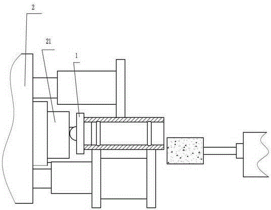
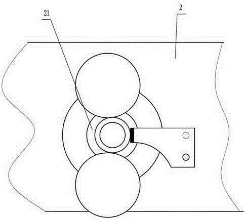
The invention discloses a method for machining end faces of a connecting shaft bearing outer ring. The method comprises the following steps of grinding the double end faces of the connecting shaft bearing outer ring obtained after quenching, conducting accurate grinding on the end faces of the connecting shaft bearing outer ring after the double end faces are ground, wherein a special rolling wheel clamp is adopted for conducting clamping in the process of conducting accurate grinding on the end faces, machining a cutting edge out of the end face of a grinding wheel, and by controlling axial movement of the grinding wheel, conducting accurate grinding machining on the end faces of the connecting shaft bearing outer ring by means of the grind wheel end face where the cutting edge is located. The special rolling wheel clamp comprises a ball-shaped backer and a rolling wheel clamp body, the rolling wheel clamp body is connected with a lathe head of a grinding lathe, when a workpiece is clamped, the ball-shaped backer is sleeved into an inner hole of the connecting shaft bearing outer ring through the boss end, and a ball joint at the other end abuts against the magnetic pole of the lathe head and the plane of a plane backer assembly. The method has the advantages of being high in machining precision and efficiency.

Description

technical field [0001] The invention relates to a processing method for the end face of the outer ring of a bearing, in particular to a processing method for the end face of the outer ring of a shaft-connected bearing. Background technique [0002] At present, the end face processing of the standard bearing outer ring generally adopts the following process: double end face grinding----use electromagnetic centerless fixture to roughly grind the outer circle----grind the end face----use electromagnetic centerless fixture to finely grind the outer circle to ensure The end face of the outer ring runs out, and this process can be guaranteed for the outer ring with a small outer ring width. The existing process is to grind the end face on a double end face grinder, and then use it on the inner circle grinding machine equipment such as 3MZS2110 The electromagnetic centerless fixture is used to grind the outer circle of the bearing outer ring. The above process must be repeated many...

Claims


Application Information

Patent Timeline
IPC IPC(8): B24B7/16B24B1/00
CPCB24B7/16B24B1/00
Inventor 彭来深蔡金友邹友明
Owner HENGYANG TEXTILE MACHINERY MANUFACTORY
Learn More