
Electric polishing machine tool

An electric, machine tool technology, applied in the direction of gear cutting machines, mechanical equipment, gear teeth, etc., can solve the problems of affecting gear quality, low degree of automation, slow processing speed, etc., to improve efficiency and gear quality, save manpower and material resources, The effect of increasing economic efficiency

Inactive Publication Date: 2015-12-30
TIANJIN JUXINGXIANGHAI MACHINERY CO LTD
View PDF4 Cites 5 Cited by
  • Summary
  • Abstract
  • Description
  • Claims
  • Application Information

AI Technical Summary

Problems solved by technology

[0002] The grinding machine tool is a gear processing machine that uses the grinding wheel as a grinding tool to process cylindrical gears or certain gears to process tool tooth surfaces. It is mainly used to eliminate deformation after heat treatment and improve the accuracy of gears. It also includes the protection of users. Grinding The machine tool is mainly aimed at the production of precision machine tools supporting gears, mining machinery, welded pipe machines, oil drilling, steel rolling mills and other gears. Due to the limitation of technical level, traditional grinding machine tools often have poor gear accuracy and slow processing speed. Moreover, most grinding machine tools are inconvenient to adjust and have poor versatility. They are only suitable for single-piece batch production. When using them, they need to artificially use intermediate tools to assist the machine in production, which wastes a lot of manpower and material resources, resulting in low productivity of the entire line and affecting production. The quality of the gear, and the degree of automation is low, which increases the cost of production

Method used


Image

  • Electric polishing machine tool

Examples


Embodiment Construction

[0012] In order to further understand the content, features and effects of the present invention, the following examples are given in detail as follows:

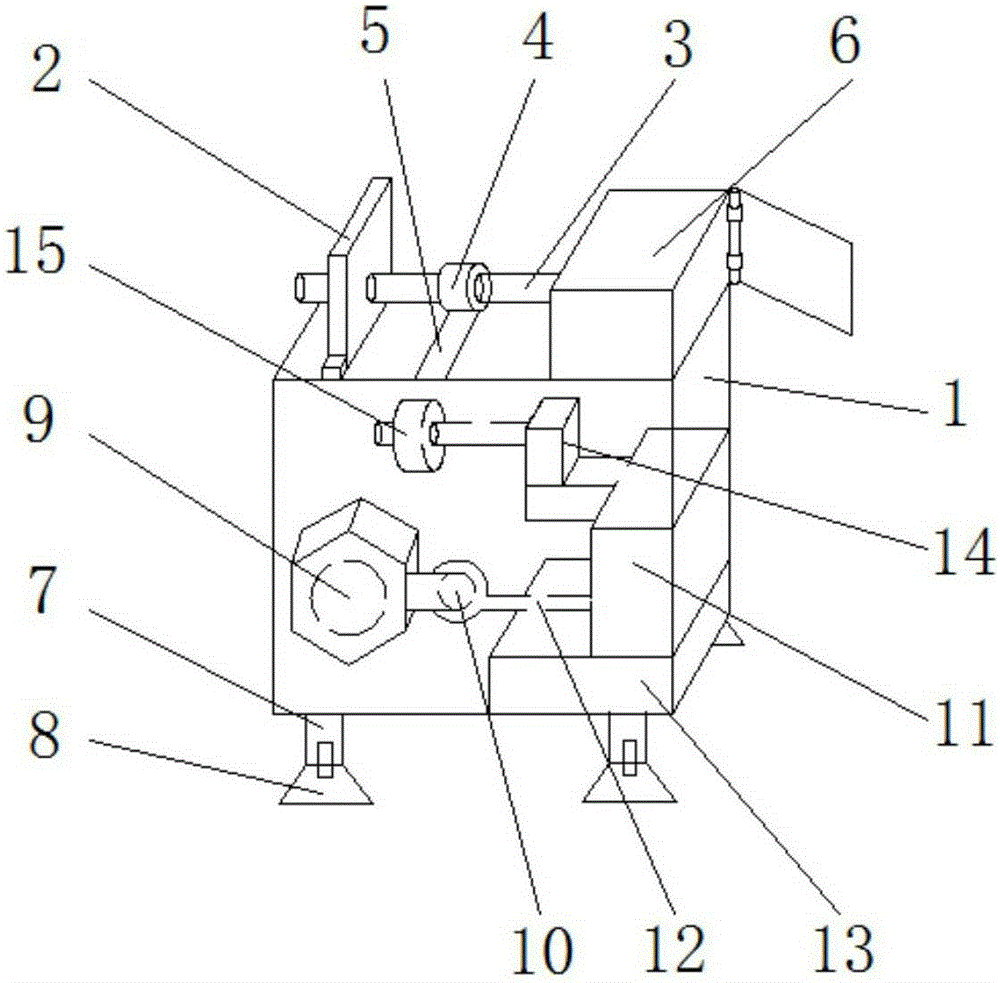
[0013] See figure 1 , The present invention includes the main body 1, the bearing turret 2, the bearing 3, the follower 4, the rotating belt 5, the processing box 6, the supporting table leg 7, the stabilizer seat 8, the high-power generator 9, the electric power output device 10, and the engine box 11. , Transmission line 12, intelligent positioning device 13, tachometer placement frame 14, and main tachometer 15. among them,

[0014] A bearing turret 2 is installed on the upper side of the main body 1, and a bearing 3 is installed on the bearing turret 2, a follower 4 is installed on the bearing 3, and a rotating belt 5 is installed on the upper side of the follower 4, and the right side of the bearing 3 is installed in the processing box Inside 6, the supporting leg 7 is arranged on the underside of the main body 1, and the ...


PUM


Abstract

The invention relates to an electric polishing machine tool, comprising a main body, a bearing rotary frame, a bearing, a following wheel, a rotary belt, a machining box, support desk legs, a stabilizing seat, a large power generator, an electric energy output device, a motor box, a transmission line, an intelligent positioning device, a rotary speed wheel supporting frame and a main rotary speed wheel; the bearing is provided with the following wheel of which the upper side is provided with the rotary belt; the large power generator is arranged in the main body; the right side of the large power generator is connected with the electric energy output device; the motor box is connected with the electric energy output device by the transmission line; the intelligent positioning device is arranged at the lower side of the motor box; the main rotary speed wheel is arranged at the left side of the rotary speed wheel supporting wheel. The novel electric polishing machine tool is higher in automatic degree, saves massive labor and material resource and is suitable for batch production of multiple parts, the machining production efficiency and gear quality are improved and economic benefits are increased.

Description

Technical field [0001] The invention relates to the field of grinding machine equipment, in particular to an electric grinding machine tool. Background technique [0002] Grinding machine tool is a gear processing machine that uses grinding wheel as an abrasive tool to process cylindrical gears or some gear tool tooth surfaces. It is mainly used to eliminate the deformation after heat treatment and improve the accuracy of the gear. It also includes the protection of the user and the grinding The machine tool is mainly aimed at the production of gear matching gears for precision machine tools, mining machinery, pipe welding machines, oil drilling, steel rolling mills, etc. Traditional grinding machine tools often suffer from poor gear accuracy and slow processing speed due to technical limitations. Moreover, most of the grinding machine tools are inconvenient to adjust and have poor versatility. They are only suitable for single-piece batch production. When using, they need to use...

Claims


Application Information

Patent Timeline
Patent Type & Authority Applications(China)
IPC IPC(8): B23F19/00B23F23/06
Inventor 崔振祥
Owner TIANJIN JUXINGXIANGHAI MACHINERY CO LTD
Learn More