
Slide fastener

A technology for zippers and zipper tapes, which is applied in the field of zippers for left and right zipper strings, and can solve problems such as being stuck on the outer wall side of the flange, unspecified distances between dimensions, and chain teeth coming out, etc.

Active Publication Date: 2015-12-23
YKK CORP
View PDF8 Cites 7 Cited by
  • Summary
  • Abstract
  • Description
  • Claims
  • Application Information

AI Technical Summary

Problems solved by technology

In addition, in the waterproof slide fastener of the modification example of patent document 2, although the protruding length of the 1st protruding part and the protruding length of the 2nd protruding part differ in the 1st stopper as mentioned above, each is not specifically demonstrated. Dimensions of protruding length, distance in the belt length direction between the front end surface of the first protrusion and the front end surface of the second protrusion, etc.
[0037] In addition, in Patent Document 2, it is not considered in the above-mentioned Patent Document 1 that when the left and right zipper strings are subjected to lateral tension in the state where the slider is in contact with the first stopper, the shoulder opening of one zipper string is not considered. The problem that side elements tend to come out of the element guide path of the slider to the outside and get stuck on the outer wall of the flange

Method used


Image

  • Slide fastener
  • Slide fastener
  • Slide fastener

Examples


Embodiment 1

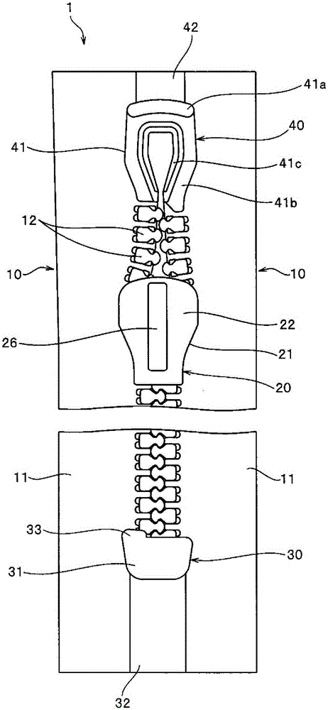
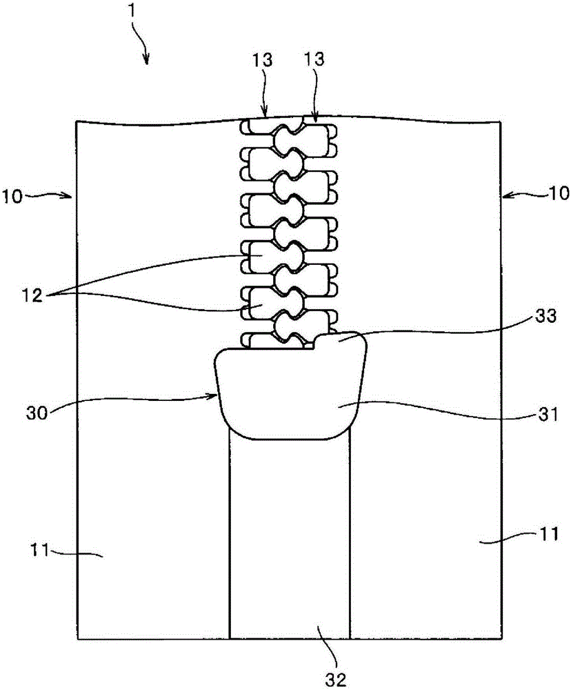
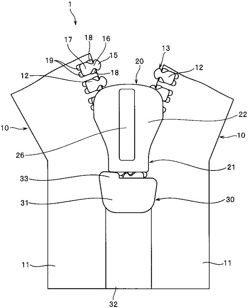
[0092] figure 1 It is a plan view which shows the slide fastener of this Example 1. figure 2 It is an enlarged bottom view showing the first stopper of the zipper. image 3 It is an enlarged plan view showing a state in which the slider is brought into contact with the first stopper in the slide fastener.

[0093] In addition, as mentioned above, in the slide fastener, the front-rear direction refers to the tape length direction of the fastener tape, and is the same linear direction as the slide direction in which the slider slides. In particular, the direction in which the slider is slid to mesh the left and right element rows is defined as the front, and the direction in which the slider is slid to release the meshing of the element rows is defined as the rear.

[0094] In addition, the left-right direction means the tape width direction of a fastener tape, and is a direction parallel to the tape surface of a fastener tape and orthogonal to a tape length direction. Espe...

Embodiment 2

[0156] Figure 6 It is a plan view which shows the slide fastener of this Example 2. Figure 7It is an enlarged perspective view showing fastener elements of the slide fastener. Figure 8 is a bottom view showing the first stop of the zipper. In addition, due to Figure 8 It is a bottom view, and the left and right directions are reversed.

[0157] The slide fastener 2 of the present embodiment 2 is constituted as a waterproof slide fastener provided with a waterproof structure in which liquid such as water does not leak from the tape front side to the tape back side (or from the tape back side to the tape front side) when the slide fastener 2 is closed. . In addition, since the slide fastener 2 of this Example 2 is lower in waterproofness than the waterproof slide fastener 1 in the said Example 1, it may also be called a waterproof slide fastener.

[0158] The waterproof zipper 2 of the present embodiment 2 has: a pair of left and right zipper stringers 50 formed by inje...


PUM


Abstract

This slide fastener (1, 2) has a stop (30, 70) against which the back opening end of a slider (20, 60) abuts. The end of the stop (30, 70) that abuts against the slider (20, 60) has a rotation-promoting section for promoting the rotation of the slider (20, 60) in a specified direction when the left or right fastener stringer (10, 50) is subjected to a transverse pulling force. Smooth sliding operation of the slider (20, 60) can thereby be stably secured because it is more difficult for the fastener elements (12, 52) to be snagged on the outer wall side of the flange sections (25a, 25b, 65a, 65b) of the slider (20, 60).

Description

technical field [0001] The present invention relates to a slide fastener in which a plurality of fastener elements are lined up on a tape side edge of a fastener tape, and more particularly to a slide fastener in which a stopper is fixed to the left and right fastener stringers so as to be continuous with one end of the left and right element rows. Background technique [0002] Generally speaking, a slide fastener has: a pair of left and right zipper fastener tapes, on the opposite tape side edges of the left and right pair of zipper tapes, an element row is formed along the tape length direction; Chain element row; the first stop piece (sometimes called bottom stop piece), which is continuous with one end of the left and right chain element row and fixed to the left and right zipper strings, and abuts against the end of the rear mouth side of the slider; and The second stopper (sometimes also referred to as a top stopper) is respectively fixed to the left and right fastener...

Claims


Application Information

Patent Timeline
Patent Type & Authority Applications(China)
IPC IPC(8): A44B19/36
CPCA44B19/36A44B19/388
Inventor 田中亮高山诚三熊亮高泽成吉
Owner YKK CORP
Learn More