Rapid video linkage realization method of power substation based on design drawing

A realization method and a technology for designing drawings, which are applied in closed-circuit television systems, calculations, image analysis, etc., can solve problems such as cumbersome operation process, difficulty in setting up, and unsuitability of monitoring technical means for remote monitoring, etc., so as to improve work efficiency and realize the method The effect of simple and easy operation, high implementability and generalizability

Inactive Publication Date: 2015-12-23
STATE GRID CORP OF CHINA +4
View PDF7 Cites 6 Cited by
  • Summary
  • Abstract
  • Description
  • Claims
  • Application Information

AI Technical Summary

Problems solved by technology

[0002] With the gradual promotion and construction of intelligent substations and unattended substations, remote monitoring and visual monitoring technologies have become important monitoring methods in power production and operation. Traditional video monitoring systems are only used for remote monitoring of substation security and fire protection. , the relevant monitoring technical means have gradually been unable to be applied to the remote monitoring in the production and operation of the power grid. The method of equipment monitoring, due to the high similarity of the appearance of most equipment, leads to cumbersome operation process and difficulty in setting up, etc. If the camera is automatically rotated to the equipment position according to the equipment object through automated technical means, it will be greatly reduced. It eliminates the large amount of configuration and operation workload required when manually setting the corresponding position or manually adjusting the monitoring angle, improves the efficiency of power equipment operation monitoring, and provides a convenient monitoring method for the safety and reliability of power grid operation.

Method used


Image

  • Rapid video linkage realization method of power substation based on design drawing
  • Rapid video linkage realization method of power substation based on design drawing
  • Rapid video linkage realization method of power substation based on design drawing

Examples


Embodiment Construction

[0035] The present invention will be further described below in conjunction with the accompanying drawings and embodiments.

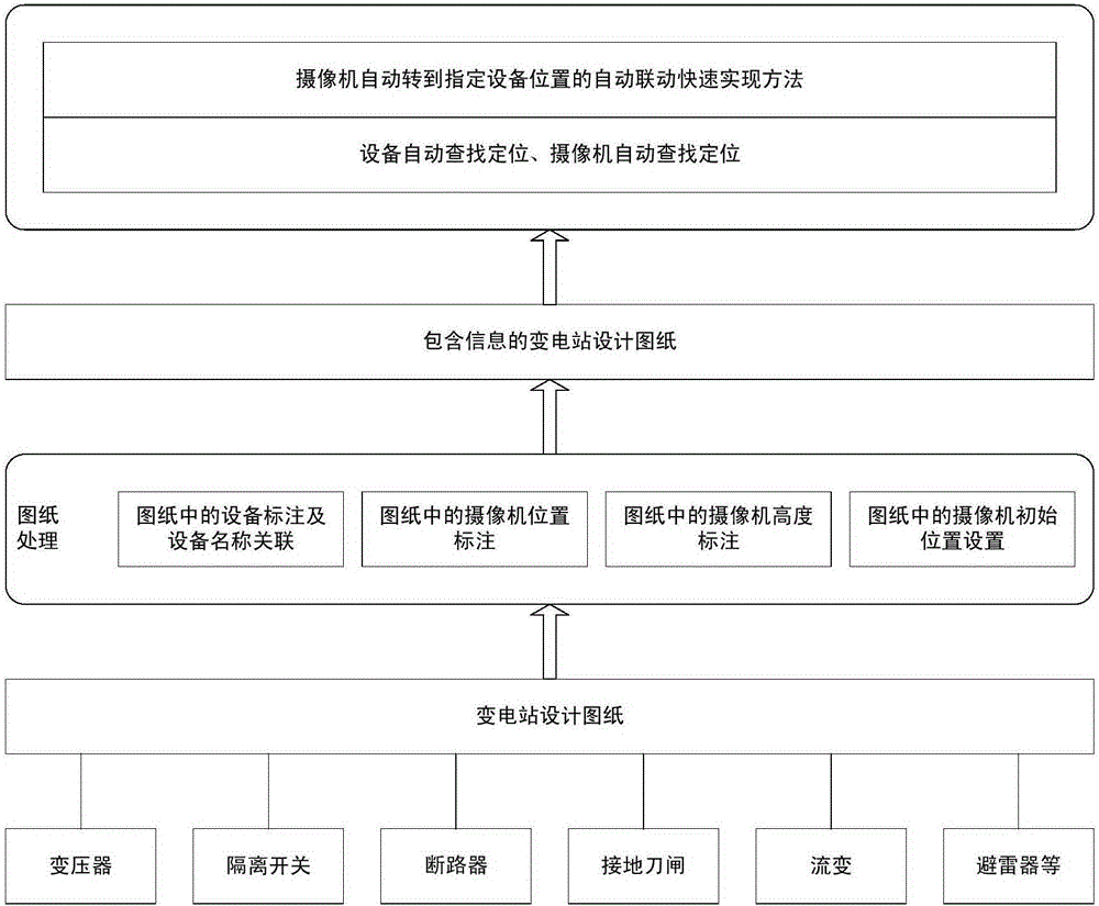
[0036] Such as figure 1 As shown, a method for quickly realizing video linkage based on design drawings of a power substation, including substation equipment construction drawings, camera installation position and height marking and initial position setting, and a method for quickly searching for the linkage relationship between cameras and equipment preset positions, is characterized in that , including the following steps:

[0037] S1. Design substation drawings according to the equipment information in the substation site;

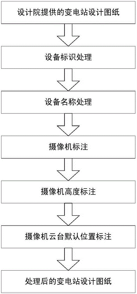
[0038] S2. Drawing processing, equipment labeling and equipment name association in the drawing, camera position and height labeling in the drawing, initial position setting of the camera pan / tilt;

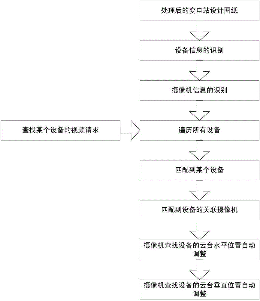
[0039] S3. A method for quickly realizing automatic linkage of equipment automatic search and positioning, camera automatic searc...


PUM


Abstract

The invention relates to a rapid video linkage realization method of a power substation based on a design drawing. The method specifically comprises the following steps: S1) designing a substation drawing according to equipment information in a substation site; S2) carrying out drawing processing: carrying out equipment marking and equipment name association, camera position and height marking and camera pan and tilt initial position setting in the drawing; and S3) carrying out automatic equipment searching and positioning and camera automatic searching and positioning, and realizing rapid automatic linkage when the camera automatically rotates to the specified equipment position. The method can provide an effective monitoring means for a power video system for automatic monitoring of power production and operation, thereby greatly reducing a lot of configuration and operation workload needed when manually setting corresponding positions or manually adjusting monitoring angles, improving work efficiency of operation monitoring of power equipment, and providing a convenient and fast monitoring means for the safety and reliability of operation of a power grid.

Description

technical field [0001] The invention relates to a method for quickly and automatically realizing the linkage relation between the camera shooting angle and the equipment position applied to the substation by the electric power system. Implementation. Background technique [0002] With the gradual promotion and construction of intelligent substations and unattended substations, remote monitoring and visual monitoring technologies have become important monitoring methods in power production and operation. Traditional video monitoring systems are only used for remote monitoring of substation security and fire protection. , the relevant monitoring technical means have gradually been unable to be applied to the remote monitoring in the production and operation of the power grid. The method of equipment monitoring, due to the high similarity of the appearance of most equipment, leads to cumbersome operation process and difficulty in setting up, etc. If the camera is automatically...

Claims


Application Information

Patent Timeline
Patent Type & Authority Applications(China)
IPC IPC(8): H04N7/18G06T7/00
Inventor 姚楠吴曦沈海平蔡越陈松石赵春雷
Owner STATE GRID CORP OF CHINA
Why Eureka
Try Eureka