Method for producing tunable non-gradient optical force on surface of liquid crystal material and metal multi-layer core-housing by slanting incidence-light

A non-gradient optical force, liquid crystal material technology, applied in the fields of biology, medicine and nano-manipulation, can solve the problems of complex incident light source, difficult to capture, untunable gradient optical force, etc., to achieve the effect of simple system and convenient operation

Inactive Publication Date: 2015-12-23
DALIAN UNIV OF TECH
View PDF2 Cites 2 Cited by
  • Summary
  • Abstract
  • Description
  • Claims
  • Application Information

AI Technical Summary

Problems solved by technology

[0003] The purpose of the present invention is to overcome the complexity of the incident light source in the traditional method of trapping and screening nano-sized molecules using gradient optical force (that is, the incident light must be a circle polarized or elliptically polarized), the limitations of screening objects (that is, nano-sized molecules must have a chiral structure), the gradient optical force generated by circularly polar

Method used


Image

  • Method for producing tunable non-gradient optical force on surface of liquid crystal material and metal multi-layer core-housing by slanting incidence-light
  • Method for producing tunable non-gradient optical force on surface of liquid crystal material and metal multi-layer core-housing by slanting incidence-light
  • Method for producing tunable non-gradient optical force on surface of liquid crystal material and metal multi-layer core-housing by slanting incidence-light

Examples


Embodiment 1

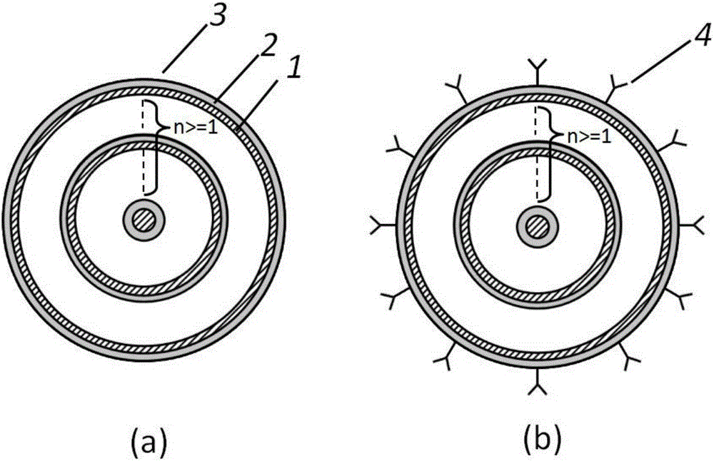
[0021] First of all, n layers (n>1) are produced by material growth process, which is composed of liquid crystal material layer 1, metal layer 2, and liquid crystal material / metal multilayer core-shell 3 alternately, as shown in the attached figure 1 (a) shown. The geometric shape and size of the liquid crystal material / metal multilayer core-shell 3 can be determined by algorithms such as finite time domain difference method and finite element method.

[0022] Secondly, nano-sized molecules 4 are attached to the outer surface of the liquid crystal material / metal multilayer core-shell 3, such as attached figure 1 (b) shown.

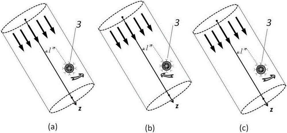
[0023] Then, the liquid crystal material / metal multilayer core-shell 3 with nanometer-sized molecules 4 attached to the surface is placed in the linearly polarized obliquely incident light beam. The Poynting vectors around the liquid crystal material / metal multilayer core-shell 3 in the light are asymmetrically distributed, that is, the total Poynting ve...


PUM

PropertyMeasurementUnit
Angle of incidenceaaaaaaaaaa

Abstract

A method for producing a tunable non-gradient optical force on the surface of a liquid crystal material and metal multi-layer core-housing by slanting incidence-light is provided. The method comprising destroying symmetric distribution of Poynting vectors around the multi-layer core-housing, enabling a total Poynting vector on the multi-layer core-housing not to be zero and producing a non-gradient optical force; and then, by changing an arranging direction (the direction of a liquid crystal molecular axis) of liquid crystal molecules in liquid crystal materials, changing the direction and the size of the total Poynting vector on the multi-layer core-housing, thus changing the direction and the size of the non-gradient optical force acted on the multi-layer core-housing by the total Poynting vector thus to regulate a moving track of the multi-layer core-housing in an incidence light field, and carrying out tunable capture and screening on nanoscale molecules adhered onto the surface of the multi-layer core-housing. Through methods such as illumination, electrification, heating and pressurization, the direction of the liquid crystal molecular axis of the liquid crystal materials in the liquid crystal material/metal multi-layer core-housing is altered.

Description

technical field [0001] The invention relates to a method for generating tunable non-gradient optical force on the surface of a liquid crystal material metal multilayer core-shell with oblique incident light, which can be applied to the fields of biology, medicine, nanometer control and the like. Background technique [0002] Optical trapping and screening of tiny objects has always been a research hotspot in the field of optics. Optical gradient force plays an important role in various optical trapping technologies, such as optical tweezers and optical bundling through optical gradient force. However, optical gradient forces have the disadvantages of complex devices, non-tunable devices, and difficulty in trapping and screening nanometer-sized molecules. In 2008, Ward, T.J. et al proposed that the optical gradient force generated by circularly polarized light can capture and separate chiral molecules with nanometer size. However, the circularly polarized incident light sti...

Claims


Application Information

Patent Timeline
IPC IPC(8): G02F1/13G02B27/28
CPCG02B27/286G02F1/1313
Inventor 曹暾
Owner DALIAN UNIV OF TECH
Why Eureka
Try Eureka