Eureka AIR delivers breakthrough ideas for toughest innovation challenges, trusted by R&D personnel around the world.

Evaporative condenser

A technology of evaporative condenser and steam outlet, which is applied in the direction of evaporator/condenser, steam/steam condenser, refrigerator, etc., which can solve the problems of energy waste, inconsistent refrigerant temperature, high cost, etc., to improve the quality of heat source, good cooling effect

Active Publication Date: 2015-12-23
SHANDONG AONAER REFRIGERATION TECH
View PDF7 Cites 4 Cited by
  • Summary
  • Abstract
  • Description
  • Claims
  • Application Information

AI Technical Summary

Problems solved by technology

[0003] The spraying device of the current evaporative condenser sprays from top to bottom when spraying, the upper coil cools quickly, and the lower coil cools slowly, resulting in inconsistent temperature of the refrigerant output from the coil, making the cooling effect not good Ideally, the cooled water part turns into water vapor and is discharged directly, resulting in a large waste of energy. The structure of the evaporative condenser is complicated. The coil is formed by connecting two adjacent straight pipes through an elbow, and high-efficiency dehydrators and other components , expensive

Method used


Image

  • Evaporative condenser
  • Evaporative condenser

Examples


Embodiment Construction

[0021] Embodiments of the present invention are further described below in conjunction with accompanying drawings:

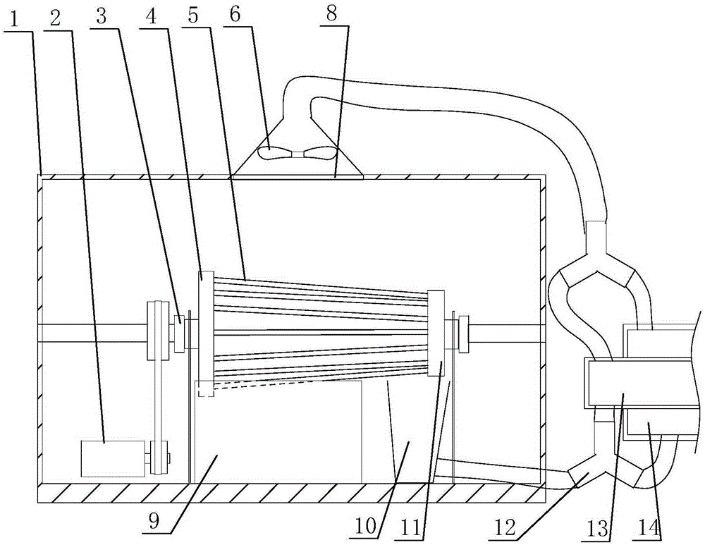
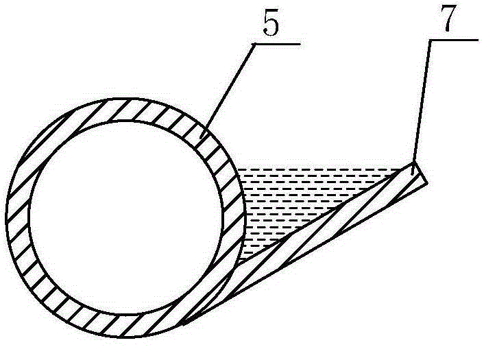
[0022] Such as figure 1 and figure 2 As shown, the evaporative condenser according to the present invention includes a shell 1, and a heat exchange assembly is arranged in the shell 1. The heat exchange assembly includes a large distribution plate 4 and a small distribution plate 11, and the large distribution plate 4 and the small distribution plate 11 are both It is an oblate cavity, straight pipes 5 are evenly distributed between the large distribution plate 4 and the small distribution plate 11, the straight pipes 5 communicate with the large distribution plate 4 and the small distribution plate 11, and the outer surfaces of the large distribution plate 4 and the small distribution plate 11 The upper part is connected to the refrigerant pipe through the sealed bearing 3, the large distribution plate 4, the small distribution plate 11 and the straight pipe ...


PUM


Abstract

The invention relates to an evaporative condenser, and belongs to the field of heat exchangers. The evaporative condenser includes a housing, wherein a heat exchanging assembly is arranged in the housing; the heat exchanging assembly includes a large distribution disk and a small distribution disk which are both oblate cavities; straight pipes are uniformly distributed between the large distribution disk and the small distribution disk; the straight pipes are communicated with the large distribution disk and the small distribution disk; the outer side surfaces of the large distribution disk and the small distribution disk are both connected with refrigerant pipes through sealed bearings; the large distribution disk, the small distribution disk, and the straight pipes form a frustum shape; a water tank is arranged below the large distribution disk; one third of the large distribution disk and part of the straight pipes are immersed into the water tank; a groove is axially formed in a coil; a water stirring piece is axially fixed on the coil and is parallel to the tangential direction of the straight pipes; a water collection tank is arranged below the small distribution disk and is connected with a sleeve through a three-way valve; one connecting opening of the three-way valve is connected with the inner pipe of the sleeve, and another connecting opening is connected with the interlayer of the sleeve. The evaporative condenser is high and uniform in cooling speed; the heat exchanged from the cooling process can realize multi-level utilization; the structure is simple, and the cost is low.

Description

technical field [0001] The invention relates to an evaporation condenser and belongs to the field of heat exchangers. Background technique [0002] The evaporative condenser is the main heat exchange equipment in the refrigeration system. Its working principle is: the superheated high-pressure refrigerant gas discharged from the compressor in the refrigeration system passes through the condensing exhaust pipe in the evaporative condenser, and the high-temperature gaseous refrigerant and The spray water and air outside the exhaust pipe perform heat exchange. That is, the gaseous refrigerant enters the exhaust pipe from the upper port and is gradually condensed into liquid refrigerant from top to bottom. The super strong wind force of the matching induced draft fan makes the spray water completely and evenly cover the surface of the coil, and the water takes advantage of the wind to greatly improve the heat exchange effect. The spray water with elevated temperature changes p...

Claims


Application Information

Patent Timeline
IPC IPC(8): F25B39/04F28B1/02
Inventor 益希亮曹海峰刘云海刘延亭刘延正许希成许文胜
Owner SHANDONG AONAER REFRIGERATION TECH
Why Eureka
Eureka Blog
Learn More