Rail components, rails, robot mobility
A mobile device and robot technology, applied in the direction of transmission devices, friction transmission devices, manipulators, etc., can solve the problems of easy deformation, affecting the accuracy of robots picking and placing workpieces, etc., to improve stability, improve production quality, and avoid left and right swings Effect
- Summary
- Abstract
- Description
- Claims
- Application Information
AI Technical Summary
Problems solved by technology
Method used
Image
Examples
Embodiment 1
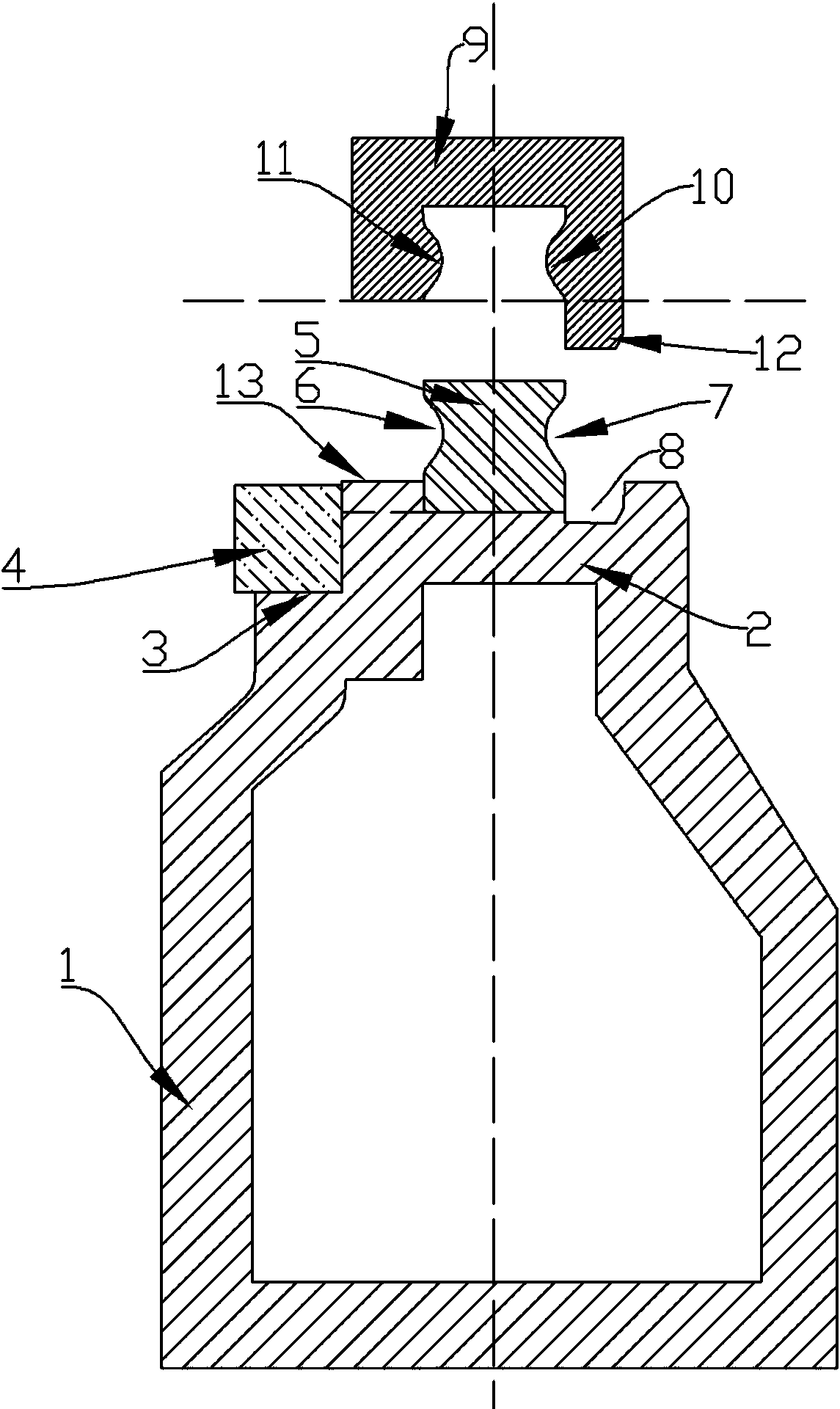
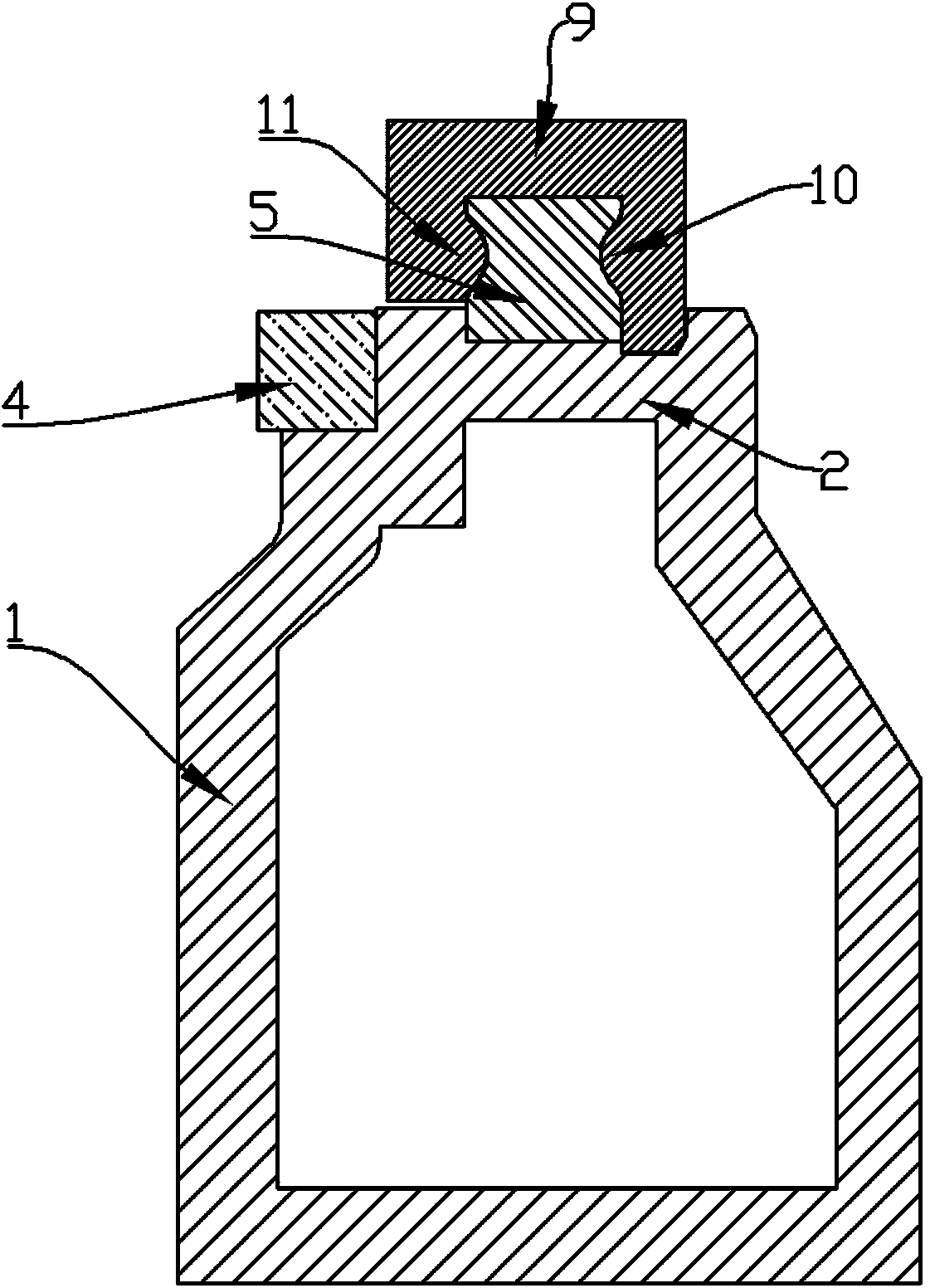
[0030] Embodiment 1: a kind of rail assembly, refer to figure 1 , figure 2 Including a base 1, a support plate 2 arranged on the upper end of the base 1; in this design, a linear guide rail belt 5 is also fixed on the support plate 2, and the linear guide rail belt 5 is arranged along the length direction of the base, and Inwardly recessed groove bands 6, 7 are respectively arranged in the middle part of the left and right side walls of the linear guide band 5, and the groove surfaces of the grooves in the groove bands 6, 7 are arc surfaces; this guide rail assembly It also includes a slider 9 whose end surface is in the shape of a "[" and is set upside down. On the inner walls of both sides of the slider 9, protrusions 10 matching the grooves on the groove belt are respectively provided. 11. The slider 9 is buckled on the linear guide rail belt 5, and the two protrusions 11 and 10 on the slider 9 are engaged with the groove belts 6 and 10 on both sides of the linear guide r...
Embodiment 2
[0032] Embodiment 2: a kind of guide rail, refer to image 3 , Figure 4 The same place as Embodiment 1 will not be repeated, and the difference is that the designed guide rail of the present invention comprises two guide rail assemblies as described in Embodiment 1; the two guide rail assemblies A, B are arranged in parallel, And between the two guide rail assemblies A and B, a connecting piece connecting the two guide rail assemblies together is provided. Described connector it comprises a plurality of transverse connecting rods 31, 32, 33 and a vertical connecting rod 34, a plurality of transverse connecting rods are equidistantly arranged in parallel between the two guide rail assemblies A, B, and the transverse connecting rods The two ends are respectively fixedly connected to the bases of the guide rail assemblies on both sides, and the vertical connecting rod 34 is arranged in the middle of a plurality of horizontal connecting rods, and is vertically arranged with the ...
Embodiment 3
[0033] Embodiment 3: a kind of robot mobile device, see Figure 1 to Figure 5 The same place as Embodiment 2 will not be repeated, and the difference is that the robot mobile device designed by the present invention includes a robot 21, a guide rail as described in Embodiment 2, and the base below the robot is fixed on two guide rails on the two slides above the assembly.
[0034] Further, the device further includes a moving plate 22, on which the robot 21 is arranged, and the moving plate 22 is fixed on the two sliding pieces 9, 9' above the two guide rail assemblies. Further, this design is on one side of the support plate 2 ( figure 1 The base 1 on the left side) is also provided with a linear step 3 arranged along the length direction of the base, and a toothed belt 4 is also provided on the linear step, and further, it is fixed under the moving plate There is a power motor (not shown in the figure), and a power gear is arranged on the output shaft of the power motor, t...
PUM
 Abstract
Description
Claims
Application Information
 - R&D
- Intellectual Property
- Life Sciences
- Materials
- Tech Scout
- Unparalleled Data Quality
- Higher Quality Content
- 60% Fewer Hallucinations
Browse by: Latest US Patents, China's latest patents, Technical Efficacy Thesaurus, Application Domain, Technology Topic, Popular Technical Reports.
© 2025 PatSnap. All rights reserved.Legal|Privacy policy|Modern Slavery Act Transparency Statement|Sitemap|About US| Contact US: help@patsnap.com


