Short spindle binding weighing device
A technology of weighing device and bundling device, which is applied to the parts and packaging of bundling machinery, can solve the problems of loose bundling, unfavorable transportation, and inability to achieve the effect of packaging.
- Summary
- Abstract
- Description
- Claims
- Application Information
AI Technical Summary
Problems solved by technology
Method used
Image
Examples
Embodiment 1
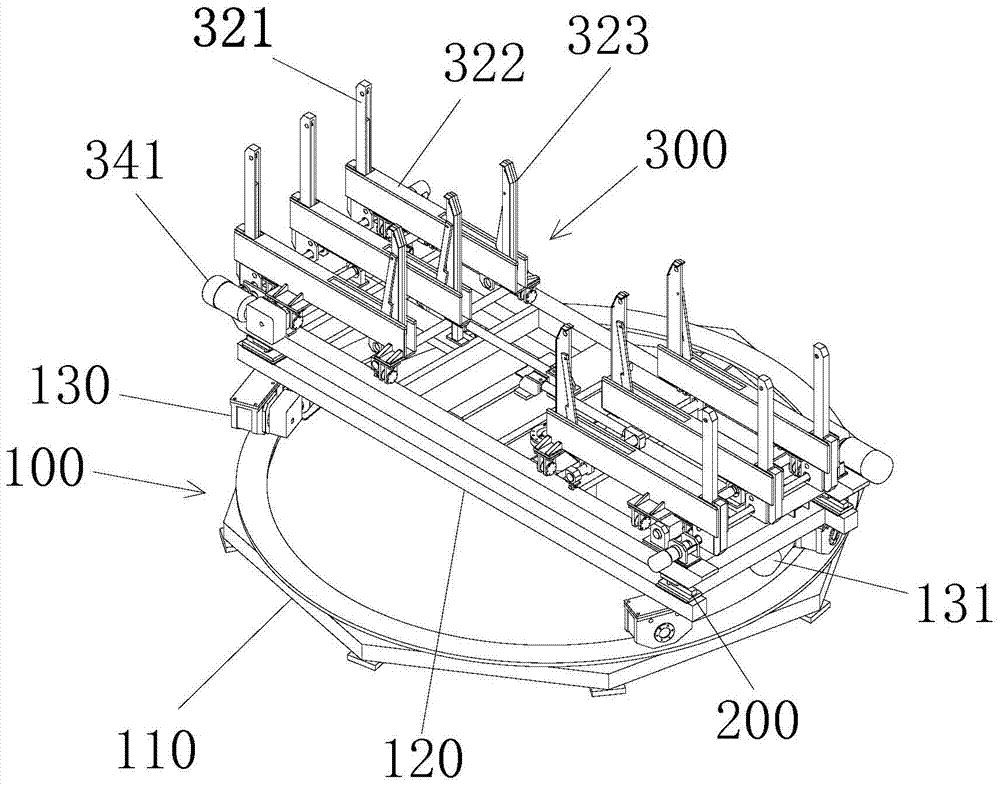
[0033] Such as figure 1 , 4 , 5, the short ingot binding weighing device includes a base 100, a weighing device 200, and a binding device 300 arranged on the weighing device 200, and the binding device 300 includes a binding frame 310 and is arranged on the binding frame Two mirrored frames 320 on the 310, the frame 320 is composed of three sets of frame bottoms 322, upper and lower movable frame walls 321 and horizontal movable frame walls 323; The device 350 drives the horizontal movable frame wall 323 to move horizontally in the groove 324; the middle group of the three groups of parallel frame bodies 320 is fixedly arranged, and the edge groups are respectively connected with a lateral drive device 340, and the lateral drive device 340 drives the edge group frame The body 320 moves to change the interval between it and the middle group frame body 320; the upper and lower movable frame walls 321 are connected with a hydraulic motor 330 through a rack, and the hydraulic mot...
Embodiment 2
[0039] Such as figure 1 , 4 As shown, this embodiment perfects the connection method between the longitudinal driving device 350 and the lateral driving device 340 and the frame body 320 . The longitudinal driving device 350 is composed of an oil cylinder 351 and a longitudinally moving roller 352 , and the track of the longitudinally moving roller 352 is arranged on the binding frame 310 . The transverse driving device 340 is composed of a geared motor 341 and a transversely moving roller 342 , and the track of the transversely moving roller 342 is arranged on the binding frame 310 . When the volume of the frame body 320 needs to be enlarged, the oil cylinder 351 can be contracted to pull out the horizontal movable frame wall 323 to expand the longitudinal volume of the frame body 320 . At the same time, the reduction motor 341 can be moved to the roller 342 to widen the gap between the edge frames 320 and expand the lateral volume of the frames 320 . When the height of th...
Embodiment 3
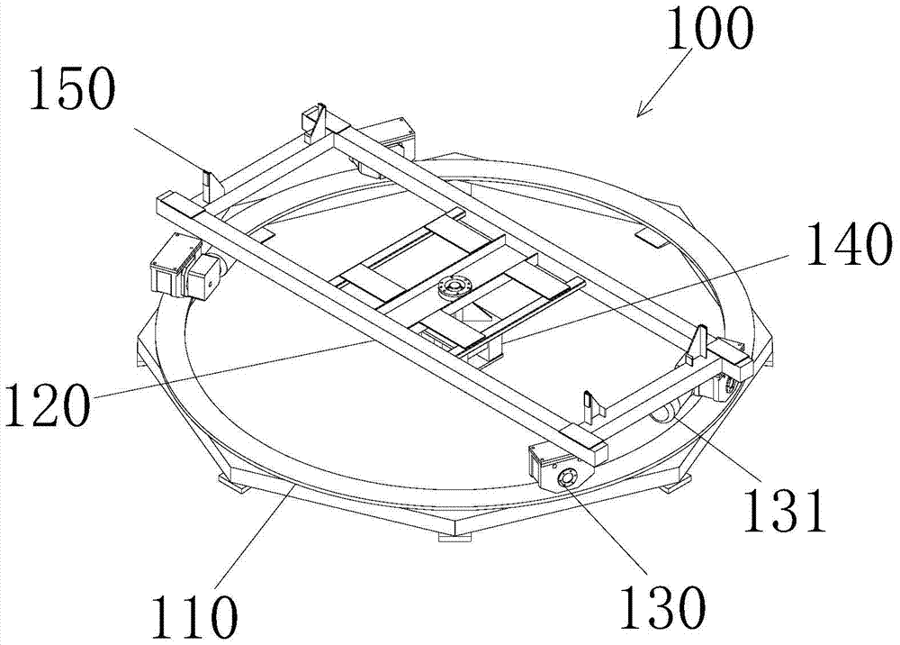
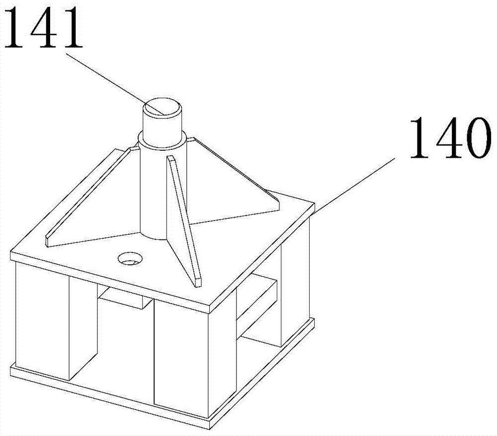
[0041] Such as figure 1 , 2 , 7, in order to more conveniently take away the framed short round ingots in this embodiment, and also in order to improve the efficiency of framing and binding, this embodiment is based on Embodiment 1 and Embodiment 2. The base 100 has been improved. The base 100 is provided with a circular track 110. The circular track 110 is connected with a rotating frame 120 through a rotating tapered roller 130. The rotating tapered roller 130 is driven by a rotating reduction motor 131. The rotating frame 120 is provided with a positioning piece 150 . The binding frame 310 is fixed or detachably mounted on the rotating frame 120 through the positioning piece 150. The binding frame 310 can be rotated under the drive of the rotation reduction motor 131, and therefore the frame body 320 mounted on the binding frame 310 can also be rotated. . After the short round ingot is framed under the effect of the manipulator, the rotary reduction motor 131 drives the ...
PUM
 Abstract
Description
Claims
Application Information
 - R&D Engineer
- R&D Manager
- IP Professional
- Industry Leading Data Capabilities
- Powerful AI technology
- Patent DNA Extraction
Browse by: Latest US Patents, China's latest patents, Technical Efficacy Thesaurus, Application Domain, Technology Topic, Popular Technical Reports.
© 2024 PatSnap. All rights reserved.Legal|Privacy policy|Modern Slavery Act Transparency Statement|Sitemap|About US| Contact US: help@patsnap.com


