
Positioning clamp and method for machining inner circle face of orthogonal shaft sleeve

A technology of positioning fixtures that are perpendicular to each other. It is used in positioning devices, manufacturing tools, metal processing equipment, etc., and can solve problems such as difficulty in ensuring machining accuracy for drilling machine reaming, and cumbersome operation steps for workpiece clamping, positioning and alignment.

Active Publication Date: 2015-12-23
FACTORY 5721 OF PLA
View PDF6 Cites 6 Cited by
  • Summary
  • Abstract
  • Description
  • Claims
  • Application Information

AI Technical Summary

Problems solved by technology

[0004] The traditional method of trimming the inner surface of the shaft sleeve is to use a drill press to ream or pass a boring machine to bore, but the drilling machine reaming has the problem that it is difficult to guarantee the machining accuracy; and the method of boring with a boring machine has the cumbersome operation steps of clamping, positioning and alignment of the workpiece Defects

Method used


Image

  • Positioning clamp and method for machining inner circle face of orthogonal shaft sleeve
  • Positioning clamp and method for machining inner circle face of orthogonal shaft sleeve
  • Positioning clamp and method for machining inner circle face of orthogonal shaft sleeve

Examples


Embodiment Construction

[0043] The present invention will be further described below in conjunction with accompanying drawing.

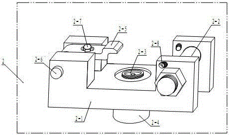
[0044] see image 3 , Figure 4 , Figure 5 , Image 6 , the positioning fixture 2 for processing the inner circular surface of the mutually perpendicular shaft sleeves according to the present invention includes a fixed seat 2-1, a positioning shaft 2-2, an adjustment sleeve 2-3, a clamping seat 2-4, a pressure plate 2-5 and a top wire 2-8; the fixed seat 2-1 is provided with a bottom plate 2-1-1, a first front side wall 2-1-2, a first rear side wall 2-1-3, and a second front side wall 2-1 -4 and the second rear side wall 2-1-5; the base plate 2-1-1 is installed on the lathe chuck, the second front side wall 2-1-4 and the second rear side wall 2-1 The positioning shaft 2-2 of the through structure is installed on the -5, and the positioning shaft 2-2 is two, and one of them is the first shaft sleeve 1-3 inner circle of the joint part, and the second shaft sleeve 1-4 is...


PUM


Abstract

The invention discloses a positioning clamp and method for machining an inner circle face of an orthogonal shaft sleeve, and belongs to the technical field of workpiece positioning clamping devices. The positioning clamp for machining the inner circle face of the orthogonal shaft sleeve comprises a fixing base, a positioning shaft, an adjusting sleeve, a clamping base, a pressing plate and jackscrews. The fixing base is provided with a base plate, a first front side wall, a first back side wall, a second front side wall and a second back side wall. The base plate is installed on a lathe chuck, positioning shafts of through structures are installed on the second front side wall and the second back side wall, and the pressing plate is assembled and hinged between the first front side wall and the first back side wall through a pressing plate pin shaft. The clamping base is installed on the base plate of the fixing base, and the adjusting sleeve is assembled on the clamping base. Each jackscrew comprises two symmetrical parts, wherein the two parts are installed on the second front side wall and the second back side wall of the fixing base respectively. By means of the positioning clamp and method, the aim that the inner circle face of the inner shaft sleeve with a vertical hole and a workpiece hole is finished on a lathe is achieved, rapid and accurate positioning of a workpiece is achieved, the product quality is guaranteed, and the work efficiency is improved.

Description

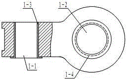
technical field [0001] The invention relates to a workpiece positioning fixture and a positioning method, in particular to a positioning fixture and a positioning method suitable for machining the inner circle surface of a shaft sleeve in a hole with two vertical holes, and belongs to the technical field of workpiece positioning and clamping devices. Background technique [0002] The turning process is mainly used to process the inner and outer rotary surfaces of the workpiece. It has the advantages of stable cutting process, high machining accuracy, simple tool structure and strong adaptability to the structure, material and production batch of the workpiece. It is widely used in the field of mechanical processing. [0003] as attached figure 1 , figure 2 Shown a joint part 1 on the landing gear of an aircraft, it is provided with two through holes whose central axes are perpendicular to each other, and the first shaft sleeve 1-3 is embedded in the first through hole 1-1,...

Claims


Application Information

Patent Timeline
IPC IPC(8): B23Q3/00
Inventor 吴建科胡树欣田德孙福才郑建华沙磊王鑫玮刘秋成李旭飞
Owner FACTORY 5721 OF PLA
Learn More