
Device and control method for using electromagnetic attractive force caused by sudden current change to form metal plate

A technology of sudden change of current and sheet metal, applied in the field of electromagnetic forming, can solve the problems of complex process and operation, inconvenient operation, etc.

Inactive Publication Date: 2015-12-23
FUZHOU UNIV
View PDF7 Cites 12 Cited by
  • Summary
  • Abstract
  • Description
  • Claims
  • Application Information

AI Technical Summary

Problems solved by technology

[0003] However, when the forming workpiece is a closed area skin or cover, the disadvantages of the electromagnetic forming equipment appear. First, the mold and the coil of the electromagnetic forming equipment are respectively placed on both sides of the workpiece, so that the whole equipment is separated. It is inconvenient to operate because of the two parts; the forming needs to set the mold in the reverse direction, and the cover needs to be disassembled first, and the process and operation become complicated

Method used


Image

  • Device and control method for using electromagnetic attractive force caused by sudden current change to form metal plate
  • Device and control method for using electromagnetic attractive force caused by sudden current change to form metal plate
  • Device and control method for using electromagnetic attractive force caused by sudden current change to form metal plate

Examples


Embodiment 1

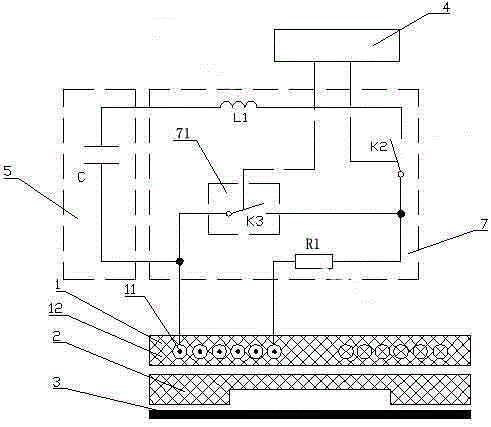
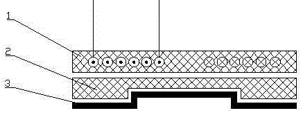
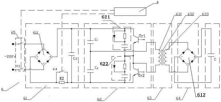
[0049] like figure 1 As shown, the present embodiment provides a device for forming sheet metal by electromagnetic attraction induced by a sudden change in current, including an execution part and a power supply system; the execution part includes a working coil 1, a mold 2, and a sheet metal 3. The mold 2 is set between the working coil 1 and the metal sheet 3, and the working coil 1 and the mold 2 are fixedly connected together as an actuator; the power supply system includes a control system 4, an energy storage system 5, a charging circuit 6 and discharge circuit 7, the charging circuit is connected to both ends of the energy storage system, the two ends of the discharge circuit are also connected to both ends of the energy storage system, the control system 4 and the charging circuit 6, The discharge circuit 7 is electrically connected, and the working coil is electrically connected with the discharge circuit 7 .

[0050] Preferably, the power supply system applies a slo...

Embodiment 2

[0069] like Figure 5 As shown, the difference from Embodiment 1 is that the sudden change of current module 71 includes an auxiliary capacitor C3' and a fast switch K3' to replace the fast short-circuit switch K3 in Embodiment 1. After the auxiliary capacitor C3' is connected in series with the fast switch K3', it is connected to the working The coils are connected in parallel. Wherein, the fast short-circuit switch K3' is a thyristor thyristor switch. Therefore, this embodiment provides a control method for a device for forming sheet metal based on the electromagnetic attraction caused by the sudden change of current described above, which mainly includes the following steps:

[0070] Step S1: placing the actuator comprising the working coil and the mold on the metal sheet to be formed;

[0071] Step S2: The control system controls the charging switch K1 in the charging circuit to be closed, the current limiting switch K4 to be open, the discharge switch K2 in the discharg...

Embodiment 3

[0076] like Figure 6 As shown, the difference from Embodiment 1 is that the sudden change of current module 71 includes a fuse switch K3 ″ to replace the fast short-circuit switch K3 in Embodiment 1, and the fuse switch K3 ″ is connected in series with the working coil. Wherein, the fuse switch K3 "includes a fuse for disconnection. Therefore, this embodiment provides a control method based on the above-mentioned sudden change in current that triggers electromagnetic attraction to form a sheet metal device, mainly including the following steps :

[0077] Step S1: placing the actuator comprising the working coil and the mold on the metal sheet to be formed;

[0078] Step S2: The control system controls the charging switch K1 in the charging circuit to be closed, the current limiting switch K4 to be open, the discharge switch K2 in the discharge circuit to be open, and the fuse switch K3" to be closed, and the external power frequency AC input current is stabilized , close th...


PUM


Abstract

The invention relates to a device and a control method for using electromagnetic attractive force caused by sudden current changes to form a metal plate. The device comprises an execution part and a power system. The execution part comprises working coils, a die and the metal plate. The die is arranged between the working coils and the metal plate. The working coils and the die are fixedly connected to serve as an actuator. The power system comprises a control system, an energy storage system, a charging loop and a discharging loop. The charging loop and the discharging loop are connected to the two ends of the energy storage system respectively in parallel. The control system is electrically connected with the charging loop and the discharging loop. The working coils are electrically connected with the discharging loop. According to the device and the control method, traditional electromagnetic forming repulsive force is converted into the attractive force, the working coils and the die can be combined into a whole, the cooperation difficulty is reduced, and the application range of an electromagnetic forming technique is enlarged in the aspect of the process.

Description

technical field [0001] The invention relates to the field of electromagnetic forming, in particular to a device and a control method for forming a metal sheet by electromagnetic attraction caused by a sudden change in current. Background technique [0002] Electromagnetic forming is mainly used in the forming and manufacturing process of conductive materials. It is a method of converting electric energy into magnetic field energy to form metal sheets. Traditional electromagnetic forming equipment often uses electromagnetic repulsion, such as the introduction of Chinese patent publication No. CN101406913A Electromagnetic forming device for sheet metal, including coil, magnetic collector, workpiece and forming die. A magnetic collector is assembled outside the coil and placed on one side of the workpiece, and the working surface of the magnetic collector for effective magnetic collection is close to the workpiece. The forming mold is located on the other side of the workpiece...

Claims


Application Information

Patent Timeline
IPC IPC(8): B21D26/14
Inventor 邓将华程溧黄伍平刘恩洋詹艳然江星莹
Owner FUZHOU UNIV
Learn More