Automatic weighing type feeding machine

An automatic weighing and feeding machine technology, applied in the field of farming machinery, can solve the problems of difficult installation, large running resistance, and high installation cost, and achieve the effects of reducing manual workload, scientific supply and adjustment, and reducing construction difficulty

Active Publication Date: 2022-02-08
青岛大牧人机械股份有限公司
View PDF3 Cites 0 Cited by
  • Summary
  • Abstract
  • Description
  • Claims
  • Application Information

AI Technical Summary

Problems solved by technology

However, the feeding accuracy of existing automatic feeders is not high. For example, in the field of poultry breeding, chicken breeding is more representative. Large-scale farms increasingly require the accuracy of feed feeding. At the same time, automatic feeders The hopper is generally located at the highest point, and the staff cannot know the amount of feed stored in the hopper and the amount of feed consumed for this feeding on the ground. It is necessary to manually climb to the highest point, and then make a judgment
At the same time, during the installation process of the automatic feeder, on-site welding is often used. Due to the constraints of the welding process and on-site environmental factors, there is a difference in parallelism between the rollers on the same side, and the rollers on both sides are dislocated when they cooperate with the track. As a result, the track of the automatic feeding machine cannot be installed, or there is serious wear on one side after installation, and the running resistance is large. The installation process often requires experienced masters to perform welding and installation, which is difficult and expensive to install.
[0003] In summary, there are obviously inconveniences and defects in the actual use of the existing technology, so it is necessary to improve

Method used


Image

  • Automatic weighing type feeding machine
  • Automatic weighing type feeding machine
  • Automatic weighing type feeding machine

Examples


Embodiment Construction

[0032] In order to make the object, technical solution and advantages of the present invention clearer, the present invention will be further described in detail below in conjunction with the accompanying drawings and embodiments. It should be understood that the specific embodiments described here are only used to explain the present invention, not to limit the present invention.

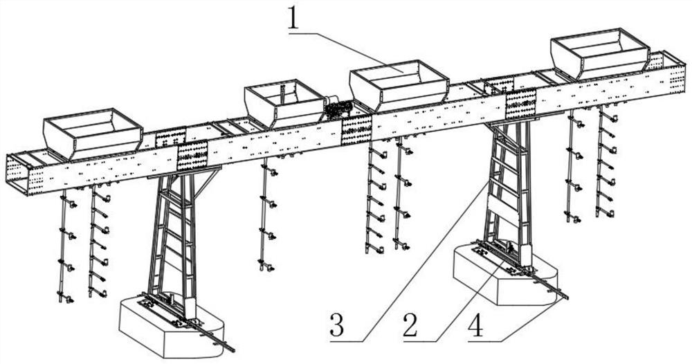
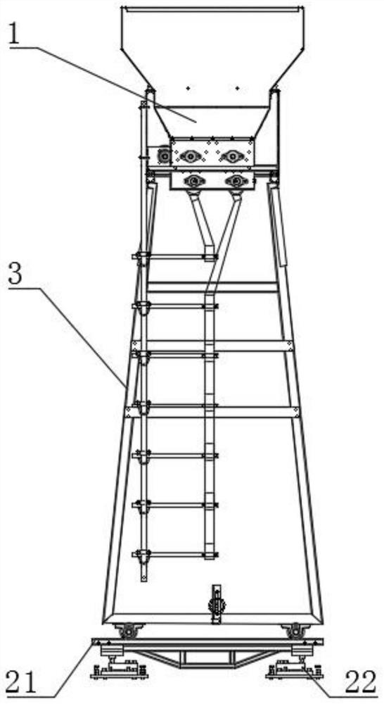
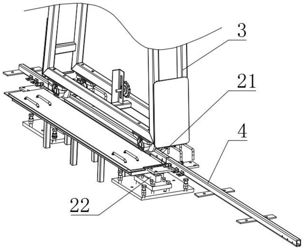
[0033] see Figure 1 to Figure 4 , The invention provides an automatic weighing feeder. The automatic weighing feeder includes: a feeding module 1, a weighing module 2 and a gantry 3, the feeding module 1 is fixedly connected to the gantry 3, the feeding module 1 synchronously transports the feed to different breeding cages, and the gantry 3 is provided with two outriggers, and the weighing module 2 is located under the gantry 3 , and the gantry 3 can slide on the weighing module 2 . The weighing module 2 includes: a load-bearing beam 21 and a pressure sensor 22 with a base. The two ends of the l...


PUM


Abstract

The invention is suitable for the technical field of breeding machinery, and provides an automatic weighing type feeding machine which comprises a feeding module, a weighing module, a portal frame, two sliding rails and a plurality of pulley assemblies; the portal frame is connected with a bearing beam in a sliding manner; and the weighing module is installed in a buried mode. The two sliding rails are arranged side by side, and the portal frame is connected with the sliding rails in a sliding mode; the plurality of pulley assemblies are symmetrically arranged at the bottom of the portal frame; and each pulley assembly comprises a roller, a fixed plate and an adjusting bracket. Therefore, the position-adjustable pulleys are arranged below the portal frame, the matching difficulty of the pulleys and the rails is reduced, the construction difficulty is reduced, meanwhile, the weighing module is arranged to integrally weigh the portal frame, the residual amount of feed in the hopper can be judged according to the weight difference value measured multiple times, the manual workload is reduced, and the feeding amount is also accurately recorded, so that the accurate feedback of the feeding amount data each time is realized.

Description

technical field [0001] The invention relates to the technical field of breeding machinery, in particular to an automatic weighing feeder. Background technique [0002] At present, in order to improve the breeding efficiency, many kinds of animals adopt large-scale breeding. For the convenience of feeding, feeders are generally used for automatic feeding. However, the feeding accuracy of existing automatic feeders is not high. For example, in the field of poultry breeding, chicken breeding is more representative. Large-scale farms increasingly require the accuracy of feed feeding. At the same time, automatic feeders The hopper is generally located at the highest point, and the staff on the ground cannot know the amount of feed stored in the hopper and the amount of feed consumed for this feeding. It is necessary to manually climb to the highest point and then make a judgment. At the same time, during the installation process of the automatic feeder, on-site welding is often ...

Claims


Application Information

Patent Timeline
IPC IPC(8): A01K39/012G01G19/52G01G23/18
CPCA01K39/0125G01G19/52G01G23/18Y02A40/81
Inventor 杨振兴范晓鹏刘国郑树利曹树涛刘福军
Owner 青岛大牧人机械股份有限公司
Why Eureka
Try Eureka