
Anti-shake device and method for road surveillance camera based on two-dimensional motion compensation

A monitoring camera and two-dimensional motion technology, applied in the field of image processing and road safety, can solve the problems of unsatisfactory clear imaging effect of the monitoring camera and long compensation delay, etc., and achieve the promotion and reduction of road network informatization and intelligence Active control to achieve the effect of imaging

Inactive Publication Date: 2018-01-30
HARBIN UNIV OF SCI & TECH
View PDF4 Cites 0 Cited by
  • Summary
  • Abstract
  • Description
  • Claims
  • Application Information

AI Technical Summary

Problems solved by technology

[0006] The device and method need three-dimensional active adjustment of the road monitoring camera, and corresponding to three steps, the compensation delay for the swing of the cantilever beam is relatively long. In the case of high-frequency swing of the cantilever beam, the clear imaging effect of the monitoring camera is not particularly ideal.

Method used


Image

  • Anti-shake device and method for road surveillance camera based on two-dimensional motion compensation
  • Anti-shake device and method for road surveillance camera based on two-dimensional motion compensation
  • Anti-shake device and method for road surveillance camera based on two-dimensional motion compensation

Examples


specific Embodiment 1

[0044] This embodiment is an embodiment of a road monitoring camera anti-shake device based on two-dimensional motion compensation.

[0045] The anti-shake device for road surveillance cameras based on two-dimensional motion compensation in this embodiment includes a two-dimensional camera adjustment module and an auxiliary target module;

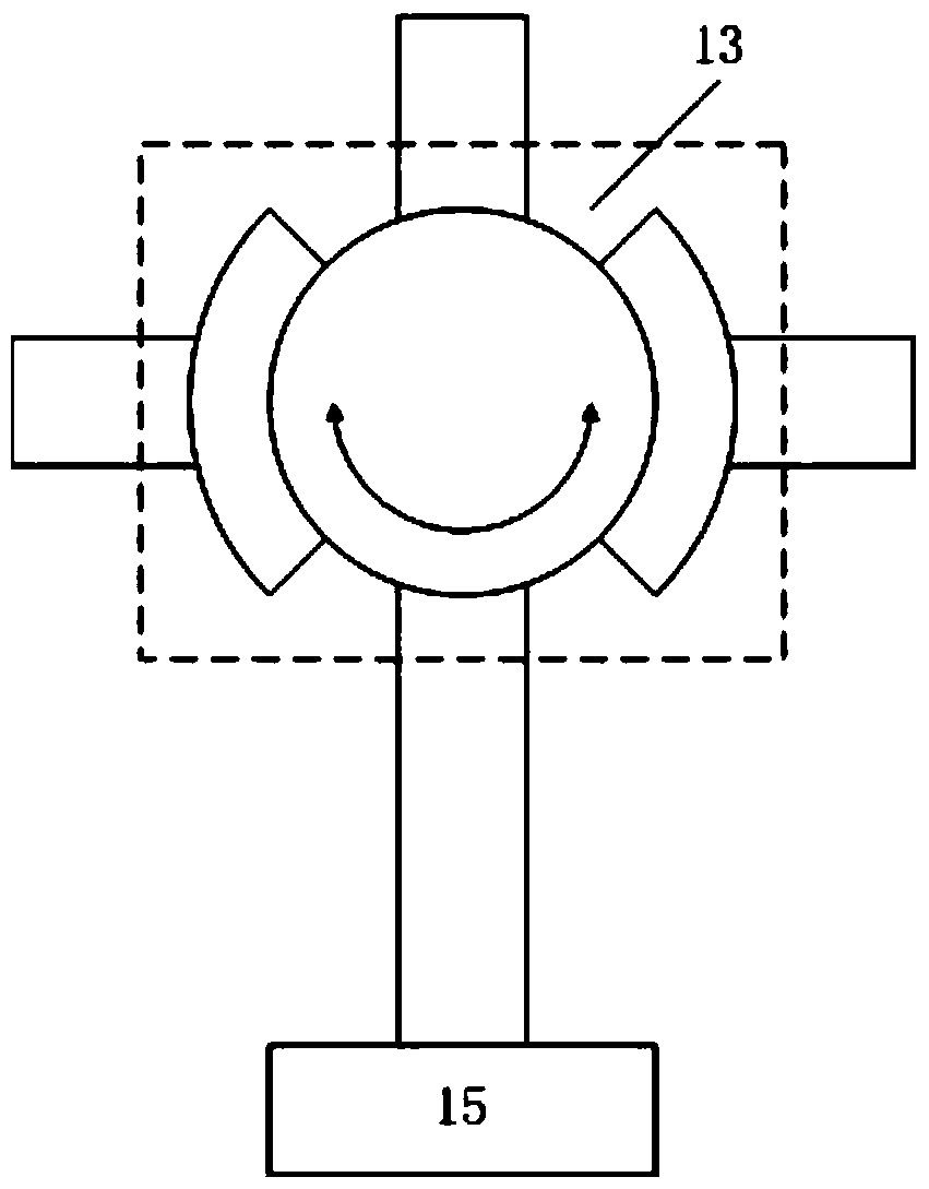
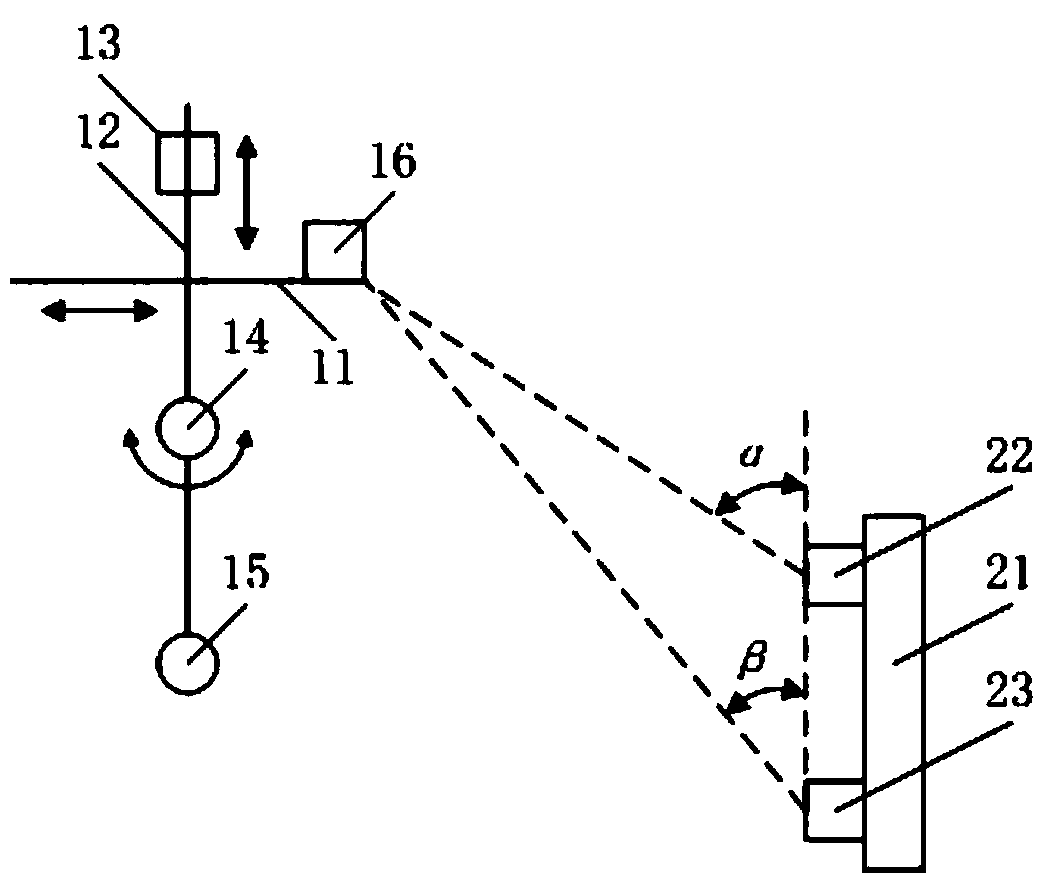
[0046] The two-dimensional camera adjustment module includes a horizontal guide rail 11 and a vertical guide rail 12. The surveillance camera 13 can move horizontally along the horizontal guide rail 11 and move up and down along the vertical guide rail 12; the bottom of the surveillance camera 13 is connected to the horizontal support end of the cantilever beam through a shaft 14 ; This part of the structure is the same as another invention patent "Anti-shake device and method for cantilever beam sway compensation for road surveillance cameras" filed by this research group, and will not be repeated in the form of drawings in this application.

[0...

specific Embodiment 2

[0050] This embodiment is an embodiment of a road monitoring camera anti-shake device based on two-dimensional motion compensation.

[0051] The anti-shake device for road surveillance cameras based on two-dimensional motion compensation in this embodiment, on the basis of specific embodiment 1, further defines that the first auxiliary target 22 and the second auxiliary target 23 are both infrared band LEDs, and the auxiliary camera 16 is infrared Band CCD. The use of infrared band devices is to take advantage of the strong anti-interference ability of infrared light to improve the anti-shake effect.

specific Embodiment 3

[0052] This embodiment is an embodiment of a road monitoring camera anti-shake device based on two-dimensional motion compensation.

[0053] The anti-shake device for road surveillance cameras based on two-dimensional motion compensation in this embodiment, on the basis of specific embodiment 1, further restricts that both the first auxiliary target 22 and the second auxiliary target 23 radiate r-rays to the auxiliary camera 16, and the auxiliary camera 16 is the r-ray receiver. The use of r-rays uses the strong penetrating power of r-rays, so that the anti-shake device of the present invention can still be used when there are obstacles such as cars and pedestrians.


PUM


Abstract

The invention relates to the technical fields of road safety and image processing, in particular to a two-dimensional motion compensation-based anti-shake device and method for a road monitoring camera; the device includes a rotating shaft, a horizontal guide rail, and a vertical guide rail, and center of gravity adjustment is arranged at the bottom of the rotating shaft block, this structural design can automatically adjust the horizontal guide rail to a horizontal state by the center of gravity adjustment block when the cantilever beam swings, and the invention patent applied by our research group "Road surveillance camera anti-shake for compensating cantilever beam swing Compared with the method, the device not only saves the level instrument and reduces the hardware cost, but also reduces the active control of one dimension in the process of compensating the cantilever beam swing, and shortens the cantilever beam swing compensation time. Under this condition, the effect of suppressing image blur and achieving clear imaging is more significant.

Description

Technical field [0001] The invention relates to the technical fields of road safety and image processing, and in particular to a road monitoring camera anti-shake device and method based on two-dimensional motion compensation. Background technique [0002] The road monitoring system is a powerful guarantee for the information and intelligence of the road network. It can make judgments on traffic violations, traffic accidents, traffic jams and other emergencies in the first time, and then adjust control parameters and formulate dispatching strategies. The two necessary conditions for achieving the above functions are: clear imaging and real-time imaging. [0003] At this stage, the road monitoring system mostly adopts the structure of installing the surveillance camera on the cantilever beam. The advantage of this structure is that the structure is simple and the installation and maintenance cost is low, but the disadvantage is that the camera will swing randomly due to the influen...

Claims


Application Information

Patent Timeline
Patent Type & Authority Patents(China)
IPC IPC(8): H04N5/232G03B5/00
Inventor 赵烟桥敬晓晔魏剑辉肖思宇张子罡翁卫东
Owner HARBIN UNIV OF SCI & TECH
Learn More