
Driving chip for display device and display device

A technology for driving chips and display devices, which is applied to static indicators, instruments, etc., and can solve problems such as abnormal display and wrong wiring connections

Active Publication Date: 2015-12-16
KUSN INFOVISION OPTOELECTRONICS
View PDF8 Cites 5 Cited by
  • Summary
  • Abstract
  • Description
  • Claims
  • Application Information

AI Technical Summary

Problems solved by technology

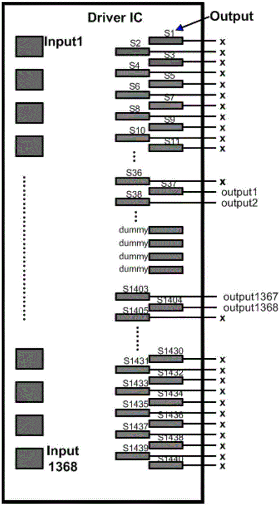
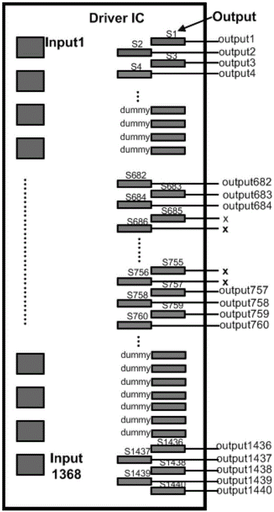
[0007] Embodiments of the present invention provide a driver chip for a display device and a display device, which solves the problem of wrong wiring connections due to different output channel sequences of the driver chip, which in turn leads to abnormal display.

Method used


Image

  • Driving chip for display device and display device
  • Driving chip for display device and display device
  • Driving chip for display device and display device

Examples


Embodiment Construction

[0037] In order to further explain the technical means and effects of the present invention to achieve the intended purpose of the invention, the specific implementation of a driver chip for a display device and a display device according to the present invention will be described below in conjunction with the accompanying drawings and preferred embodiments. Mode, structure, feature and effect thereof are as follows in detail.

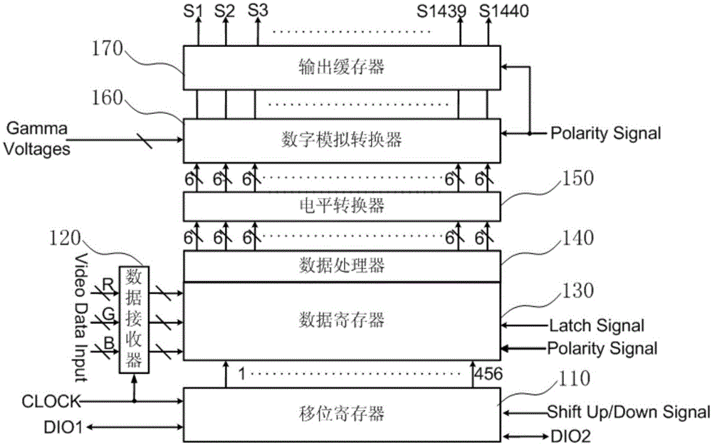
[0038] Such as figure 2 Shown is a schematic diagram of a driving chip for a display device provided by Embodiment 1 of the present invention. As shown in the figure, the driver chip includes: a shift register 110 , a data receiver 120 , a data register 130 , a data processor 140 , a level shifter 150 , a digital-to-analog converter 160 and an output buffer 170 .

[0039] Wherein, the shift register 110 is used to receive a clock signal (CLOCK) and a shift register signal (ShiftUp / DownSignal), and control the data register 130 to store data according...


PUM


Abstract

The embodiment of the invention discloses a driving chip for a display device and a display device. The driving chip comprises a shift register, a data receiver, a data register, a data processor, a level converter, a digital-to-analog converter, and an output buffer. The data processor is electrically connected with the data register and comprises n input channels and m output channels. Any input channel is electrically connected with the m output channels. The data processor is used for controlling any input channel to be communicated with one output channel according to a pre-stored control instruction in order that any input channel outputs received corresponding channel data via the output channel communicated with the any input channel, wherein the n output channels communicated with the n input channels output effective channel data, and the (m-n) output channels not communicated with any input channel output no channel data. The data processor may flexibly adjust the sequence of the output channels and prevent a problem of display abnormality caused by erroneous wire connection of the driving chip.

Description

technical field [0001] Embodiments of the present invention relate to display driving technologies, and in particular, to a driving chip for a display device and a display device. Background technique [0002] The driver chip of the existing liquid crystal display module has an output channel, wherein the driver chip transmits the data signal to the corresponding data line through the output channel, and the driver chip transmits the gate signal to the corresponding gate line through the output channel. [0003] It is known that the number of data lines and gate lines of a liquid crystal display device is large, and the corresponding number of output channels of the driver chip is large. When the driver chip drives the gate lines, a part of the output channels may be selected to output the gate signal, and the driver chip When driving the data lines, some of the output channels may be selected to output data signals, so the output channels of the driver chip output correspon...

Claims


Application Information

Patent Timeline
IPC IPC(8): G09G3/36
Inventor 何甲王立明蔡浩
Owner KUSN INFOVISION OPTOELECTRONICS
Learn More