System and method for measuring flow velocity and flow in slope soil
A flow measurement and measurement system technology, which is applied in measurement devices, soil material testing, instruments, etc., can solve the problems of inability to realize and difficult to monitor the flow velocity in the soil, and achieve the effect of being easy to carry.
- Summary
- Abstract
- Description
- Claims
- Application Information
AI Technical Summary
Problems solved by technology
Method used
Image
Examples
Embodiment 1
[0051] Build slope runoff plots on the slope along the trend of the slope from top to bottom. The standard runoff slope is 15 degrees, and the slope range designed for general tests is 10-24 degrees.
[0052] Set sealing baffles on the left and right boundaries of the slope runoff plot and the upper boundary of the high terrain respectively. The depth of the sealing baffles inserted into the slope is generally 200mm-300mm; the height of the sealing baffles above the ground is generally 100mm- 200mm; the sealing baffle is a steel plate or cement board; relying on the above three sealing baffles (that is, the sealing baffles set on the left and right boundaries of the slope runoff plot and the upper boundary of the high terrain) to make the runoff of the plot and the two sides and the upper slope runoff isolation.
[0053] The soil inflow collection facility 2 is arranged at the lower boundary of the low terrain of the slope runoff plot, thereby forming a slope runoff plot compo...
Embodiment approach 1
[0063] Implementation Mode 1: Measurement of soil flow velocity and dynamic calculation of soil flow in the case of natural rainfall
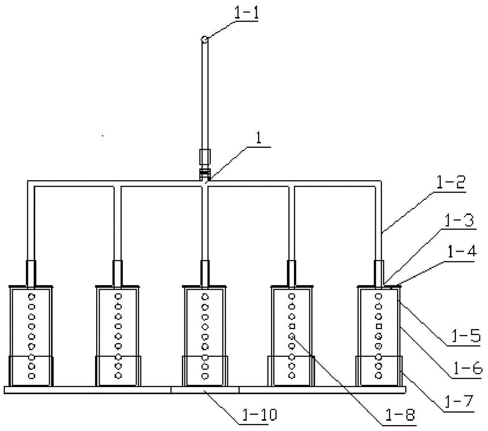
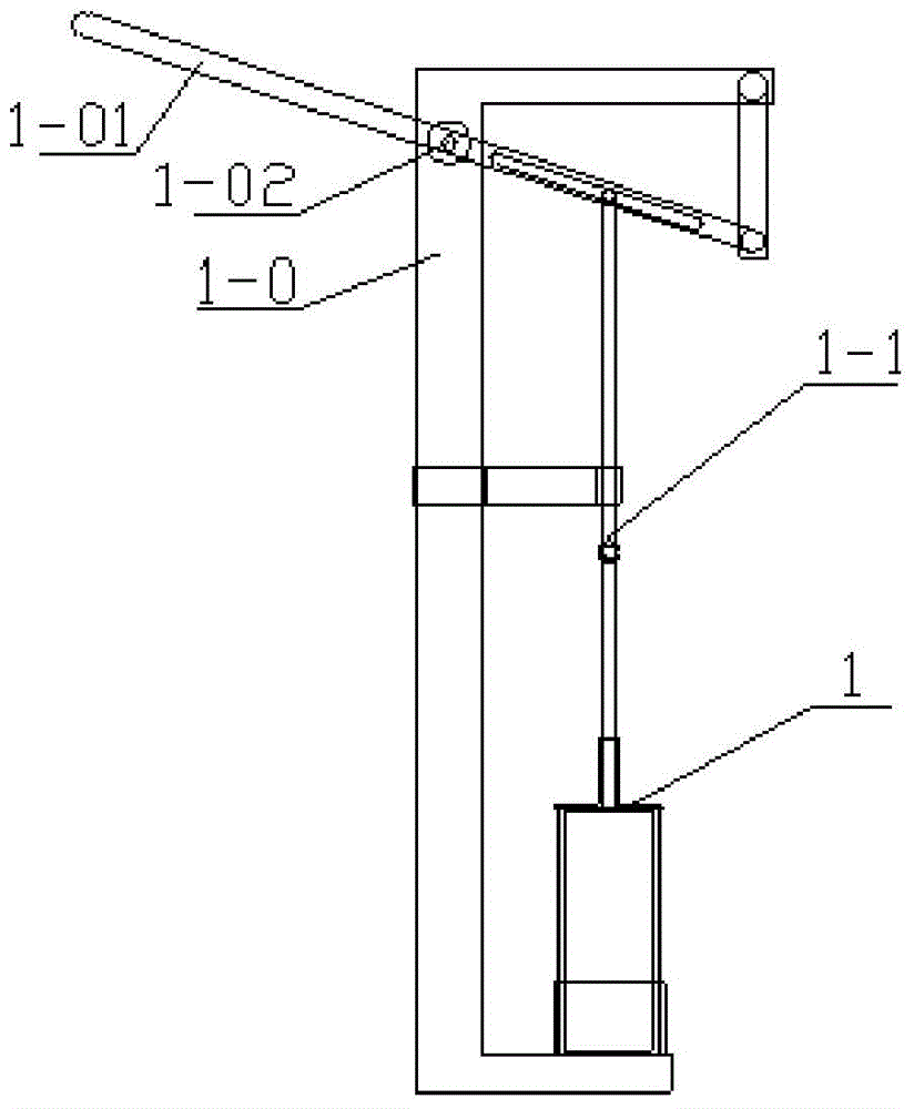
[0064] first step. According to the test requirements, as mentioned above, firstly, a slope runoff zone with a specific slope and independent water system is built on the slope to ensure that the soil layer on the slope does not interfere; The width of the plot is consistent and the depth reaches the vertical section of the parent material layer, and the soil flow collection facility 2 is installed in the excavated section. Soil middle flow collection device 2 adopts layered design, each layer is designed according to 150mm, generally designed with 4-5 layers, the number of layers can be adjusted according to the depth of the excavated section; Agent delivery facility 1. According to the requirements of the test design, the tracer injection facilities should be placed on the slope at a certain depth, generally 50mm-100mm (see figure 1 ).
...
Embodiment approach 2
[0073] Implementation Mode 2: Measurement of soil flow velocity and calculation of soil flow dynamics under artificially simulated rainfall conditions
[0074] Because the intensity of natural rainfall is easy to fluctuate and difficult to control, the duration of rainfall will also change, sometimes for a long time, sometimes for a short time. Therefore, for decades, the study of the hydrodynamic process of slope runoff in this research field has generally been carried out by artificially simulating rainfall.
[0075] first step. Ditto.
[0076] second step. After the construction and installation of the slope runoff plot and the related tracer delivery facility 1 and soil midflow collection facility 2, firstly, 4 (2 on each side) pressure-controlled, two-way Side spray, portable simulated rainfall device (conventional use). According to the test design, the rain intensity is controlled through the pressure and nozzle aperture size, and a certain duration of rainfall is s...
PUM
| Property | Measurement | Unit |
|---|---|---|
| height | aaaaa | aaaaa |
Abstract
Description
Claims
Application Information
 - R&D Engineer
- R&D Manager
- IP Professional
- Industry Leading Data Capabilities
- Powerful AI technology
- Patent DNA Extraction
Browse by: Latest US Patents, China's latest patents, Technical Efficacy Thesaurus, Application Domain, Technology Topic, Popular Technical Reports.
© 2024 PatSnap. All rights reserved.Legal|Privacy policy|Modern Slavery Act Transparency Statement|Sitemap|About US| Contact US: help@patsnap.com


