Fluid control system

A technology of control system and fluid control device, which is applied in the direction of wellbore/well components, sealing/isolation, drilling pipe, etc., and can solve problems such as drilling efficiency and adverse effects on production

Inactive Publication Date: 2013-12-25
HYDRIL USA DISTRIBUTION LLC
View PDF7 Cites 0 Cited by
  • Summary
  • Abstract
  • Description
  • Claims
  • Application Information

AI Technical Summary

Problems solved by technology

This operation often takes the better part of a day and has a significant detrimental effect on drilling efficiency and production

Method used


Image

  • Fluid control system
  • Fluid control system
  • Fluid control system

Examples


Embodiment Construction

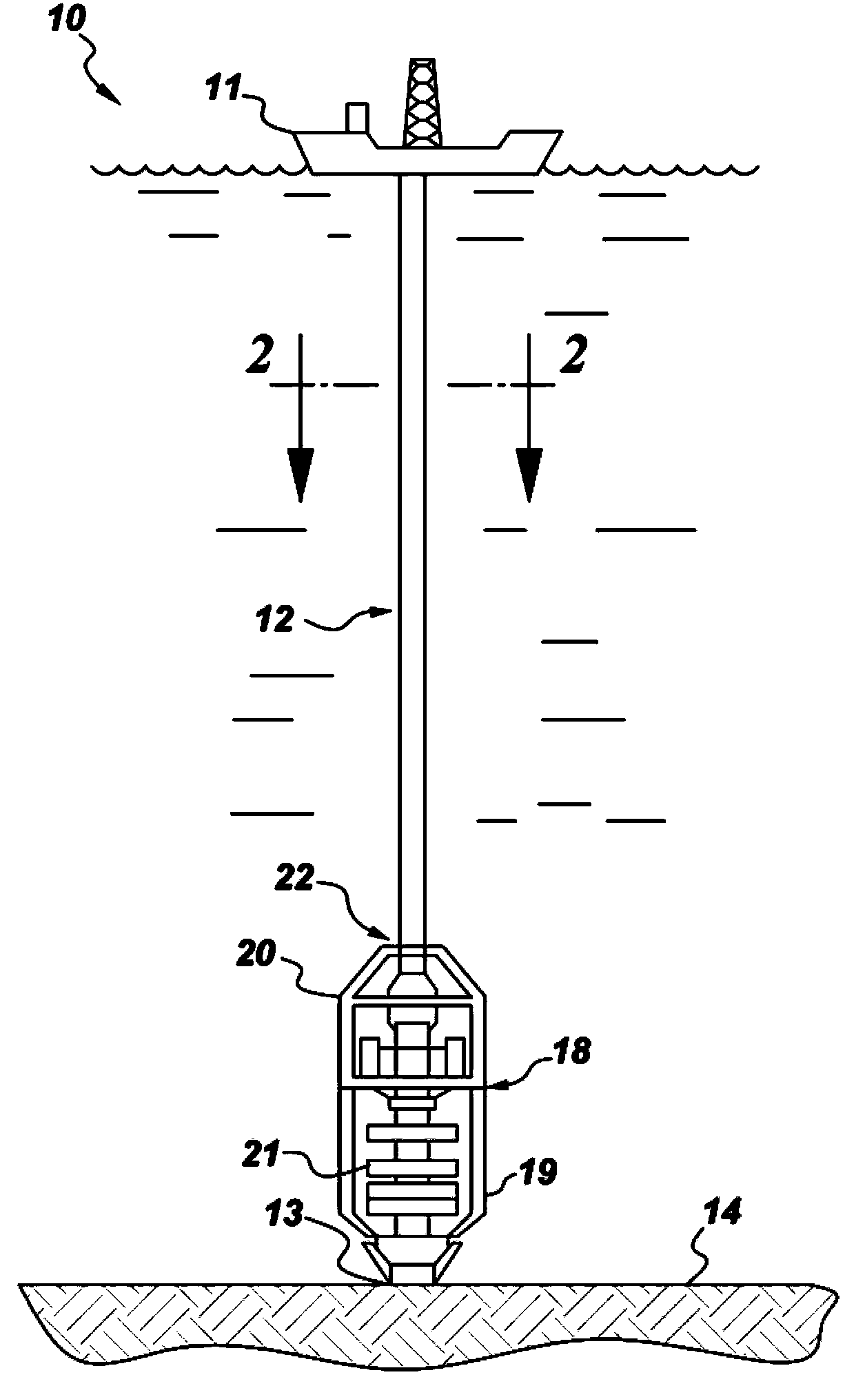
[0016] figure 1 Shown is a schematic diagram of an embodiment of the drilling system 10 of the present invention. In the embodiment of the present invention, the drilling system 10 can be used to drill wells to explore hydrocarbons, such as Fossil Fuels. In a non-limiting example, the wellbore includes an onshore well and an offshore well. In one example, the drilling system 10 is used to drill offshore boreholes.

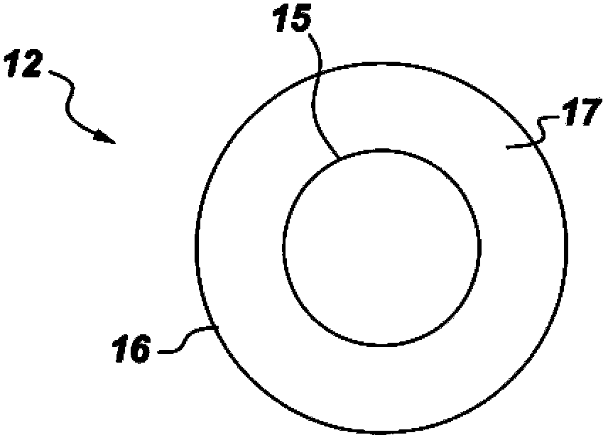
[0017] Such as figure 1 As shown, the drilling system 10 generally includes a platform 11 on the water surface and a drilling assembly 12 connecting the platform 11 and the wellhead on the seabed 14. Drilling set 12 (e.g. figure 2 (Shown) includes a drill string 15, a drill bit (not shown) and a riser 16 to drill the well.

[0018] The drill string 15 includes a drill pipe, which is formed by connecting multiple pipes with a certain length end to end. The drill bit is installed at one end of the drill string 15 and rotatably excavates under the seabed 14. The drill...


PUM


Abstract

The invention relates to a fluid control system for drilling well holes. The fluid control system comprises a guide pipe, an acoustic sensing device and a fluid control device, wherein the guide pipe is provided with a channel capable of containing a drill stem, and a returned drilling fluid can pass through the channel; the acoustic sensing device can be used for monitoring the flow speed of the returned drilling fluid. The fluid control device can be used for responding to an accident monitored by the sensing device so as to control the flow speed of the returned drilling fluid, and is adjacent to the sensing device.

Description

Technical field [0001] The present invention relates to a fluid control system that can be used to control fluid flow, and more particularly to a fluid control system that can be used to control the flow of returning drilling fluid (or returning drilling fluid, Returning Drilling Fluids) during drilling of oil wells, such as offshore oil wells. The fluid control system where Kick occurs. Background technique [0002] The search and exploration of hydrocarbons (hydrocarbon) from the subsurface formation (Subsurface Formation), such as petroleum, has been conducted for decades. Due to the limited production capacity of surface-based oil wells, exploration of hydrocarbons from subsea oil wells has attracted attention. [0003] Generally, when drilling an offshore oil well (Offshore Well), a rotatable drill bit (Drill Bit) is set on a drill string (Drill String) to drill a well hole from under the seabed. Surface platforms, such as offshore platforms or drilling ships, control the dr...

Claims


Application Information

Patent Timeline
Patent Type & Authority Applications(China)
IPC IPC(8): E21B21/08
CPCE21B21/10E21B21/08E21B47/107E21B21/001E21B47/001E21B17/01E21B19/002E21B21/106E21B33/064
Inventor 罗伯特.A.乔吉克里斯多佛.E.沃尔夫刘逢甦刘莉法赛德.高瑞朴
Owner HYDRIL USA DISTRIBUTION LLC
Why Eureka
Try Eureka