Splash-proof joint of square drill rod

A technology of anti-splash joints and drill pipe joints, which is applied in the field of oil drilling valves, and can solve problems such as troublesome operation, high cost, and easy blockage

Active Publication Date: 2015-12-16
BC P INC CHINA NAT PETROLEUM CORP +1
View PDF5 Cites 8 Cited by
  • Summary
  • Abstract
  • Description
  • Claims
  • Application Information

AI Technical Summary

Problems solved by technology

[0004] The technical problem to be solved by the present invention is to provide a kelly splash-proof jo

Method used


Image

  • Splash-proof joint of square drill rod
  • Splash-proof joint of square drill rod
  • Splash-proof joint of square drill rod

Examples


Embodiment Construction

[0022] The specific embodiments of the present invention will be described in further detail below in conjunction with the drawings and embodiments. The following examples are used to illustrate the present invention, but not to limit the scope of the present invention.

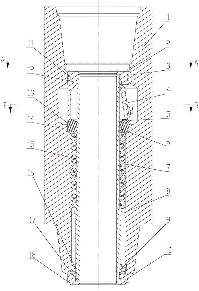
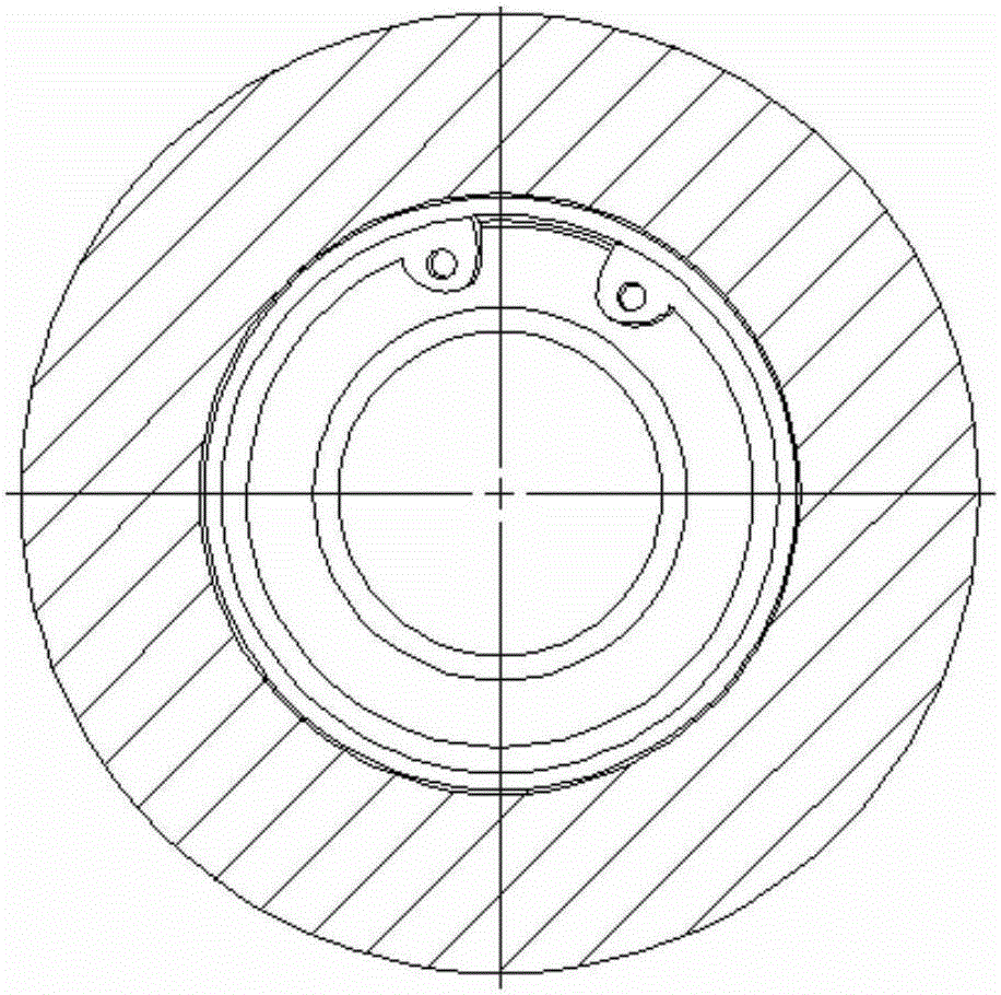
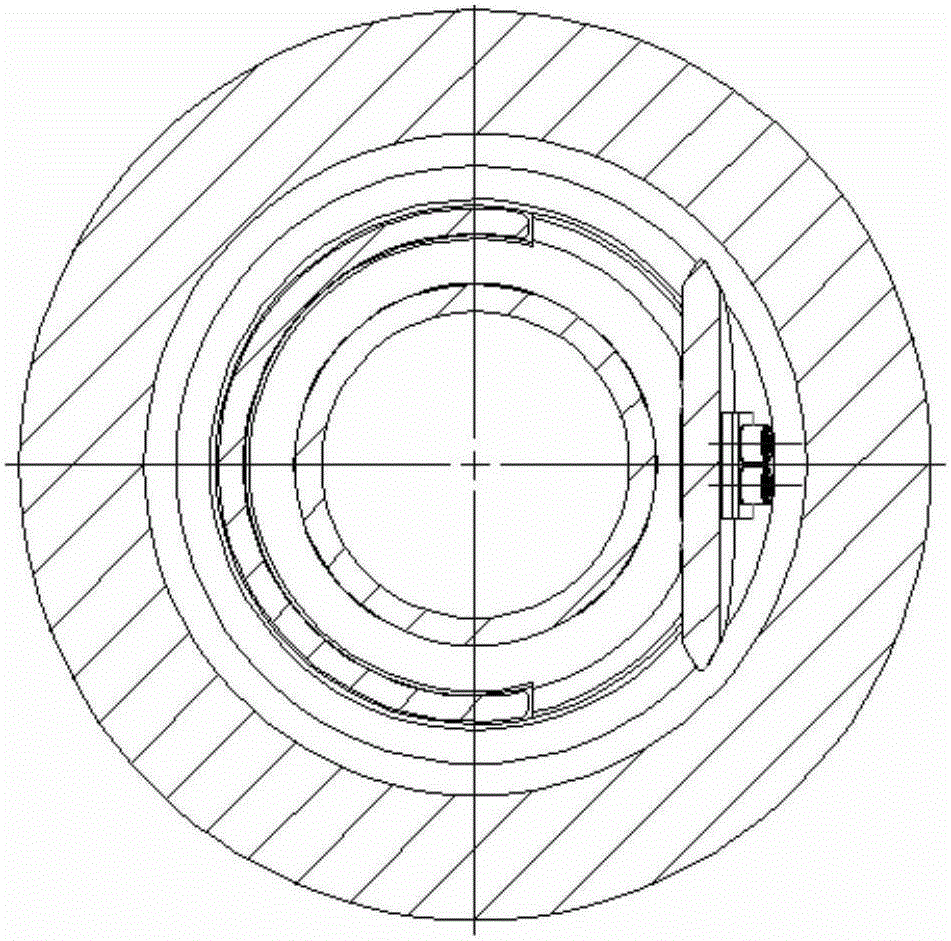
[0023] Such as Figure 1-3 As shown, the present invention provides a splash-proof joint for a kelly rod. The splash-proof joint is composed of a brake piston cylinder 15, a spring check valve plate 4, and an outer cylinder 1. Use the tightening and unloading of the thread of the outer cylinder and the lower drill rod to control the axial movement of the brake piston cylinder; use the position of the brake piston to control the switch of the spring check valve plate; the outer cylinder and the brake piston cylinder during drilling A sealed space is formed between them, so that the valve plate in the sealed space does not contact the mud environment; when the thread is removed, the brake piston cylinder releases...


PUM


Abstract

The invention relates to the technical field of valves for petroleum drilling, in particular to a splash-proof joint of a square drill rod. The splash-proof joint is mounted on the lower portion of the square drill rod and comprises a braking piston barrel, a spring check valve plate and an outer barrel, drill rod threads are formed on two sides of the outer barrel, an upper female buckle of the outer barrel is connected with the square drill rod while the lower male buckle of the same is connected with a drill rod joint, a valve seat is mounted at the bottom of a shoulder inside the outer barrel, a limiting sleeve is mounted on the upper portion of the valve seat, and two elastic clamping springs are mounted on the upper portion of the limiting sleeve and clamped in a clamping spring groove of the outer barrel to limit the limiting sleeve and the valve seat at corresponding positions of the outer barrel. During well drilling, a full-bore drilling liquid circulating passage with diameter phi greater than 58mm is provided; during buckle releasing, a water hole of the square drill rod is sealed, and enough pressure of an upper mud liquid column can be borne; during well drilling, a splash-proof valve plate does not contact with mud, so that prolonging of service life of the valve plate is facilitated; the splash-proof joint is simple in structure and needless of external power, and energy resources are saved.

Description

Technical field [0001] The invention relates to the technical field of valves for oil drilling, and in particular to a kelly pipe splash-proof joint installed at the lower part of the kelly pipe. Background technique [0002] After the kelly is disconnected from the drilling or the drilling, there will always be hoses and residual drilling fluid on the upper part of the riser flowing from the joint where the kelly is unloaded to the drilling platform. This not only wastes drilling fluid, but also deteriorates the environment and endangers the health of operators. Currently, two methods are usually used: The first method is to install a plug valve under the kelly to avoid the above problems. However, the plug valve has the problems of high cost, troublesome manual operation, and easy to hold the pump after forgetting to open it. The second method is to install a mud splash valve with an arrow spring valve core at the lower part of the kelly. However, due to the arrow-shaped struc...

Claims


Application Information

Patent Timeline
IPC IPC(8): E21B17/042E21B21/10
Inventor 王军刘伟唐立伟黄国辉张琳
Owner BC P INC CHINA NAT PETROLEUM CORP
Why Eureka
Try Eureka