
A robotic automatic grinding device for large workpieces

A technology for large workpieces and industrial robots, which is applied in the direction of grinding/polishing safety devices, grinding workpiece supports, grinding machines, etc. Safe and guaranteed cleaning effect

Active Publication Date: 2017-10-10
HARBIN UNIV OF COMMERCE
View PDF7 Cites 0 Cited by
  • Summary
  • Abstract
  • Description
  • Claims
  • Application Information

AI Technical Summary

Problems solved by technology

[0004] The present invention aims to solve the problems of low grinding efficiency, low grinding precision, poor processing environment and difficulty in realizing continuous operation in the processing of large workpieces in the existing processing technology, and provides a robot automatic grinding machine for large workpieces

Method used


Image

  • A robotic automatic grinding device for large workpieces
  • A robotic automatic grinding device for large workpieces
  • A robotic automatic grinding device for large workpieces

Examples


specific Embodiment approach 1

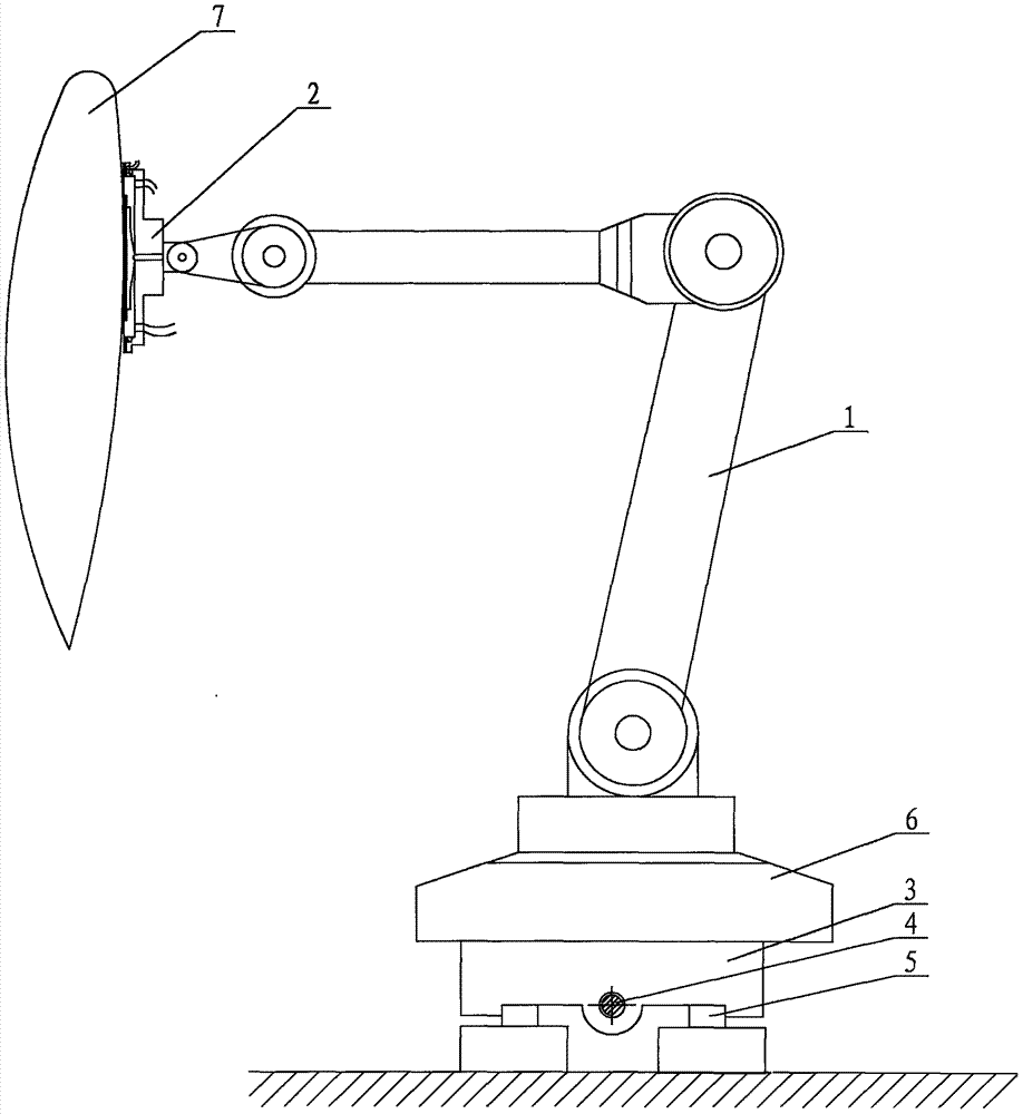
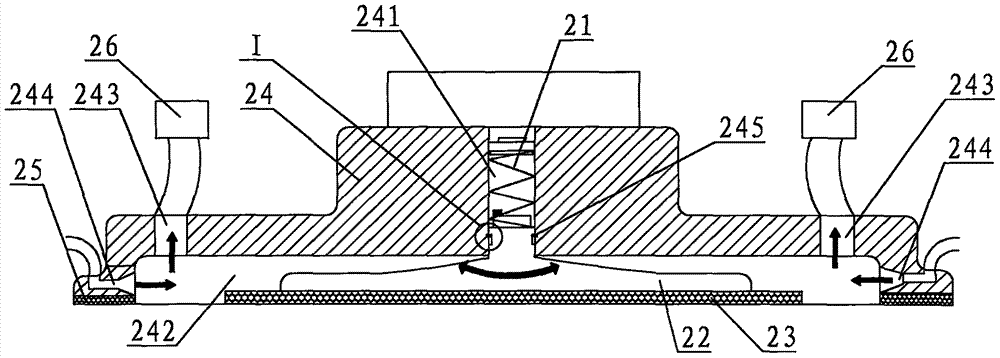
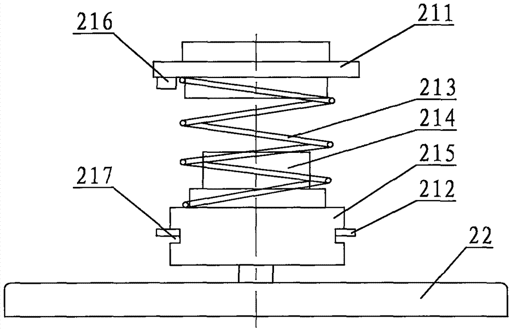
[0017] Specific implementation mode one: combine Figure 1 to Figure 5 Describe this embodiment, this embodiment comprises industrial robot 1, grinding device 2, mobile platform 3, lead screw 4, track 5 and base 6, the tail of industrial robot 1 is fixed on the mobile platform 3 by base 6, mobile platform 3 is threadedly connected with the lead screw 4, the lead screw 4 is driven by the driving motor, the mobile platform 3 is slidably connected with the rail 5, the length direction of the guide rail 5 is parallel to the length direction of the workpiece fixture (not shown), and the grinding device 2 is installed in the industrial The end of the robot 1; the grinding device 2 includes a buffer assembly 21, a vacuum chuck 22, grinding paper 23, a resin cover 24, an annular felt 25 and two negative pressure adsorption devices 26, and the buffer assembly 21 includes an upper contact plate 211, a retaining spring 212, buffer spring 213, drive motor 214, lower contact plate 215 and ...

specific Embodiment approach 2

[0018] Specific implementation mode two: combination figure 2 and image 3 The present embodiment will be described. The material of the vacuum chuck 22 of the present embodiment is cemented carbide. The rigidity of cemented carbide is good, which can maintain a large enough contact force between the vacuum chuck 22 and the workpiece 7 . Other components and connections are the same as those in the first embodiment.

specific Embodiment approach 3

[0019] Specific implementation mode three: combination Figure 5 To describe this embodiment, the lower end surface of the vacuum chuck 22 of this embodiment is provided with an annular groove 222 . By adopting a suction cup with an annular groove, it is easy to form a negative pressure on the surface of the suction cup, thereby realizing the adsorption of the grinding paper. Other compositions and connections are the same as those in Embodiment 1 or 2.


PUM


Abstract

The invention discloses an automatic polishing robot device for a large-sized workpiece in order to solve the problems that the polishing efficiency is low, the polishing precision is low, the processing environment is poor, the continuous operation is difficultly realized and the like when the large-sized workpiece is processed by the existing processing technology. A grinding device is mounted at the tail end of an industrial robot; a buffer spring is arranged between an upper contact plate and a lower contact plate; clamp springs are arranged in annular grooves; a drive motor is arranged in the buffer spring; grinding paper is closely attached on the lower end face of a vacuum chuck; a concave cavity is formed in the lower end face of a resin cover; the vacuum chuck is arranged in the concave cavity; a buffer assembly is arranged in a center hole of the resin cover; the clamp springs are clamped in radial grooves of the center hole; annular felt is attached to the lower end face of the resin cover; two air suction openings and two blowing openings are formed in the resin cover; each negative pressure absorption device is corresponding to one blowing opening; and each negative pressure absorption device is connected with the corresponding blowing opening by a pipeline. The robot automatic polishing device for the large-sized workpiece is used for the surface grinding processing of the large-sized workpiece.

Description

technical field [0001] The invention relates to a grinding machine for grinding the surface of large workpieces, in particular to a robot automatic grinding machine for large workpieces. Background technique [0002] Large ships have been in sea service for a long time, and the hull will be eroded by seawater, so the hull needs to be maintained by grinding and spraying. Wind turbines usually operate in dry desert areas with strong winds and poor air quality or seasides with salt fog and humidity. Wind turbine blades are often damaged by sand damage, salt fog erosion, and the adsorption of insects and dirt in the air, which destroys their surface quality. Grinding and reworking blades is a common method of restoring their surface quality. Whether it is a ship hull or a wind turbine blade, they are all large-sized workpieces. For the processing of large-sized workpieces, traditional processing equipment is incompetent due to the limited size of the workbench and the limited t...

Claims


Application Information

Patent Timeline
Patent Type & Authority Patents(China)
IPC IPC(8): B24B27/00B24B41/06B24B55/00B24B55/06
CPCB24B27/0084B24B41/06B24B55/00B24B55/06
Inventor 卜迟武邓兆军唐庆菊孙智慧
Owner HARBIN UNIV OF COMMERCE
Learn More