
A mounter driven by a linear motor

A linear motor and placement machine technology, applied in electrical components, printed circuits, printed circuit manufacturing, etc., can solve the problems of surface mount requirements that cannot be achieved with the same suction and placement, the speed and accuracy cannot be met, and the transmission accuracy can be achieved. High, improve the effect of production efficiency

Active Publication Date: 2018-06-05
HEFEI INSTITUTES OF PHYSICAL SCIENCE - CHINESE ACAD OF SCI +1
View PDF7 Cites 0 Cited by
  • Summary
  • Abstract
  • Description
  • Claims
  • Application Information

AI Technical Summary

Problems solved by technology

In recent years, with the development of the LED industry, new challenges have been brought to the overall performance of the LED placement machine. At present, most of the mainstream LED placement machines in the market use the transmission mode of the servo motor ball screw, which cannot achieve simultaneous suction and placement. The surface mount requirements, speed and accuracy cannot meet the requirements of modern technology

Method used


Image

  • A mounter driven by a linear motor
  • A mounter driven by a linear motor
  • A mounter driven by a linear motor

Examples


Embodiment Construction

[0025] The technical solutions in the embodiments of the present invention will be clearly and completely described below in conjunction with the embodiments of the present invention. Apparently, the described embodiments are only some of the embodiments of the present invention, not all of them. Based on the embodiments of the present invention, all other embodiments obtained by persons of ordinary skill in the art without making creative efforts belong to the protection scope of the present invention.

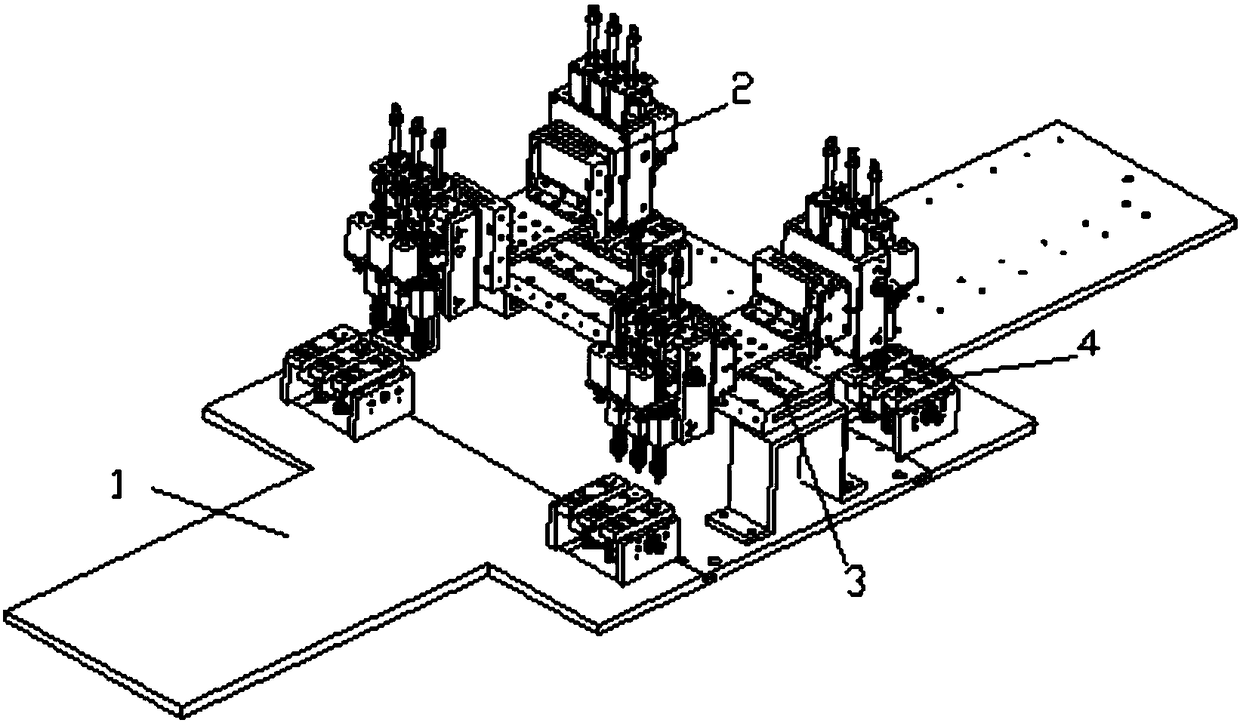
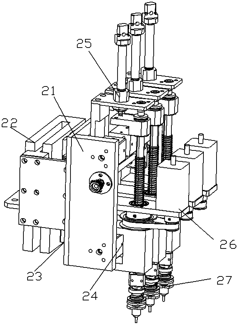
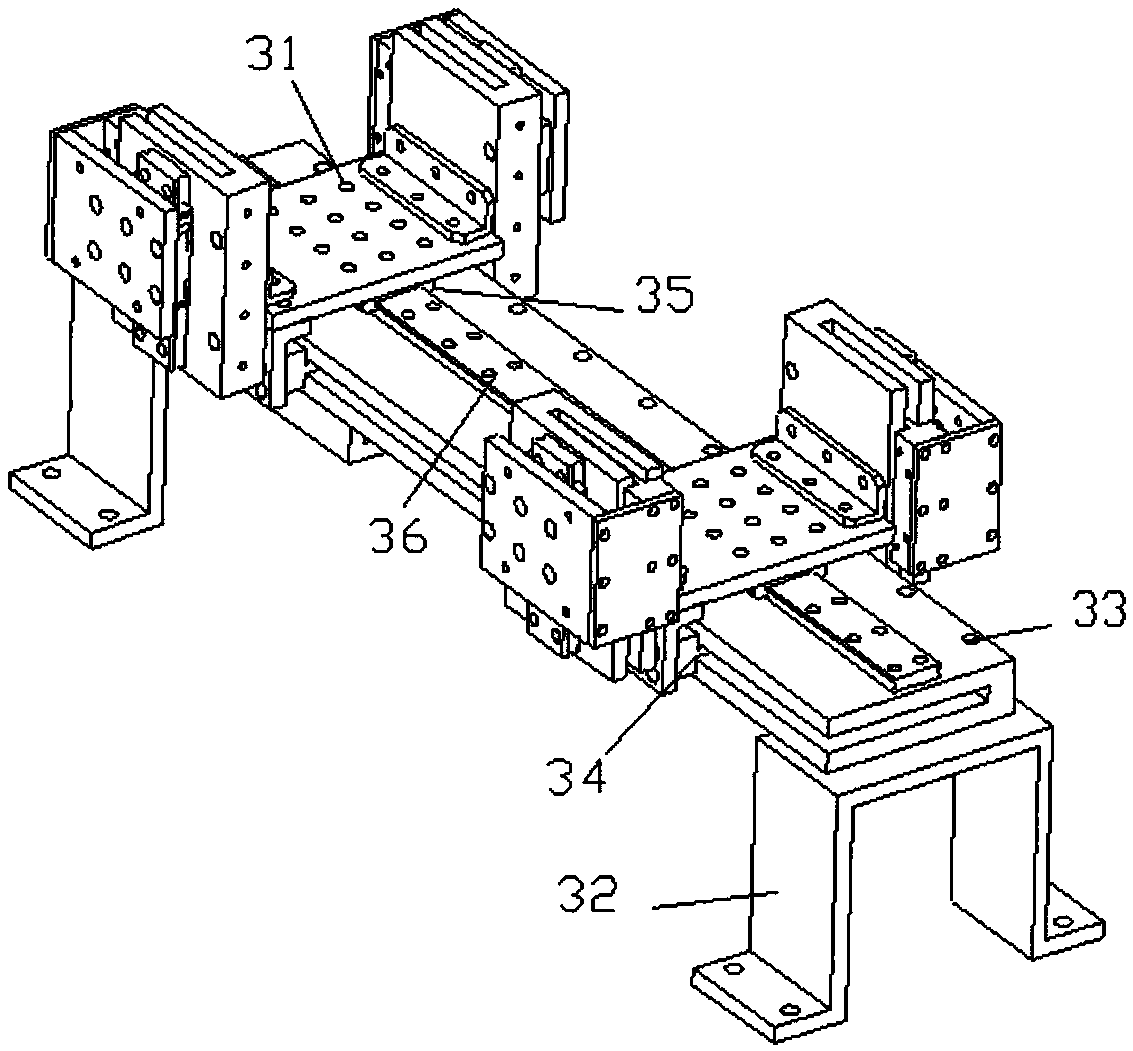
[0026] see Figure 1~6 , in an embodiment of the present invention, a placement machine driven by a linear motor includes a base plate 1, a mounting head 2, a mounting beam 3 and a feeder 4; the feeder 4 is arranged on the base plate 1, and the mounting beam 3 is set on the bottom plate 1, and the mounting head 2 is set on the upper part of the mounting beam 3;

[0027] The mounting head 2 includes a head fixing plate 21, a linear motor 22, a guide rail A23, an equidistant a...


PUM


Abstract

The invention discloses a linear motor driven chip mounter. The chip mounter comprises a base plate, a mounting head part, a mounting beam and a feeder; the feeder is arranged on the base plate; the mounting beam is arranged on the base plate; the mounting head part is arranged at the upper part of the mounting beam; the chip mounter is driven by the linear motor; the mounting head part and the feeder adopt equally spaced adjusting mechanisms, so that the chip mounter is suitable for mounting electronic components at different spacings; the mounting head part adopts a dual-lifting mechanism, so that the purpose of material suction and material dropping at the same time is fulfilled; and in addition, the chip mounter is simple in structure, convenient to operate, high in mounting speed, high in position precision and capable of effectively enhancing the productivity.

Description

technical field [0001] The invention relates to the field of SMT equipment, in particular to a placement machine driven by a linear motor. Background technique [0002] Facing the increasingly fierce competition in the electronic market, the production and manufacturing equipment of electronic products is developing towards high speed and high precision, especially the surface mount equipment of electronic components. In recent years, with the development of the LED industry, new challenges have been brought to the overall performance of the LED placement machine. At present, most of the mainstream LED placement machines in the market use the transmission mode of the servo motor ball screw, which cannot achieve simultaneous suction and placement. The surface mount requirements, speed and accuracy cannot meet the requirements of modern technology. Contents of the invention [0003] The purpose of the present invention is to provide a placement machine driven by a linear mo...

Claims


Application Information

Patent Timeline
Patent Type & Authority Patents(China)
IPC IPC(8): H05K3/30
CPCH05K3/303H05K2203/0195
Inventor 孙鹏孙继斌王容川冯宝林吴晶华叶晓东
Owner HEFEI INSTITUTES OF PHYSICAL SCIENCE - CHINESE ACAD OF SCI
Learn More