
A Piezoelectric-Electromagnetic Composite Energy Harvester

A composite energy harvester technology, applied to piezoelectric effect/electrostrictive or magnetostrictive motors, generators/motors, electrical components, etc., can solve problems such as inability to use external power supply and complicated circuits. Achieve the effect of avoiding large volume of battery power supply, simple structure, and strong environmental adaptability

Inactive Publication Date: 2018-02-02
BEIJING INSTITUTE OF TECHNOLOGYGY
View PDF4 Cites 0 Cited by
  • Summary
  • Abstract
  • Description
  • Claims
  • Application Information

AI Technical Summary

Problems solved by technology

[0003] The known measurement and control systems all need external power supply, and the external power supply and the sensor must be connected by wires, and the wiring is complicated and convenient; and it cannot be used in an environment without power supply or in an extremely harsh environment (such as the energy supply of an oil drilling drill bit positioning sensor). External power supply

Method used


Image

  • A Piezoelectric-Electromagnetic Composite Energy Harvester
  • A Piezoelectric-Electromagnetic Composite Energy Harvester
  • A Piezoelectric-Electromagnetic Composite Energy Harvester

Examples


Embodiment 1

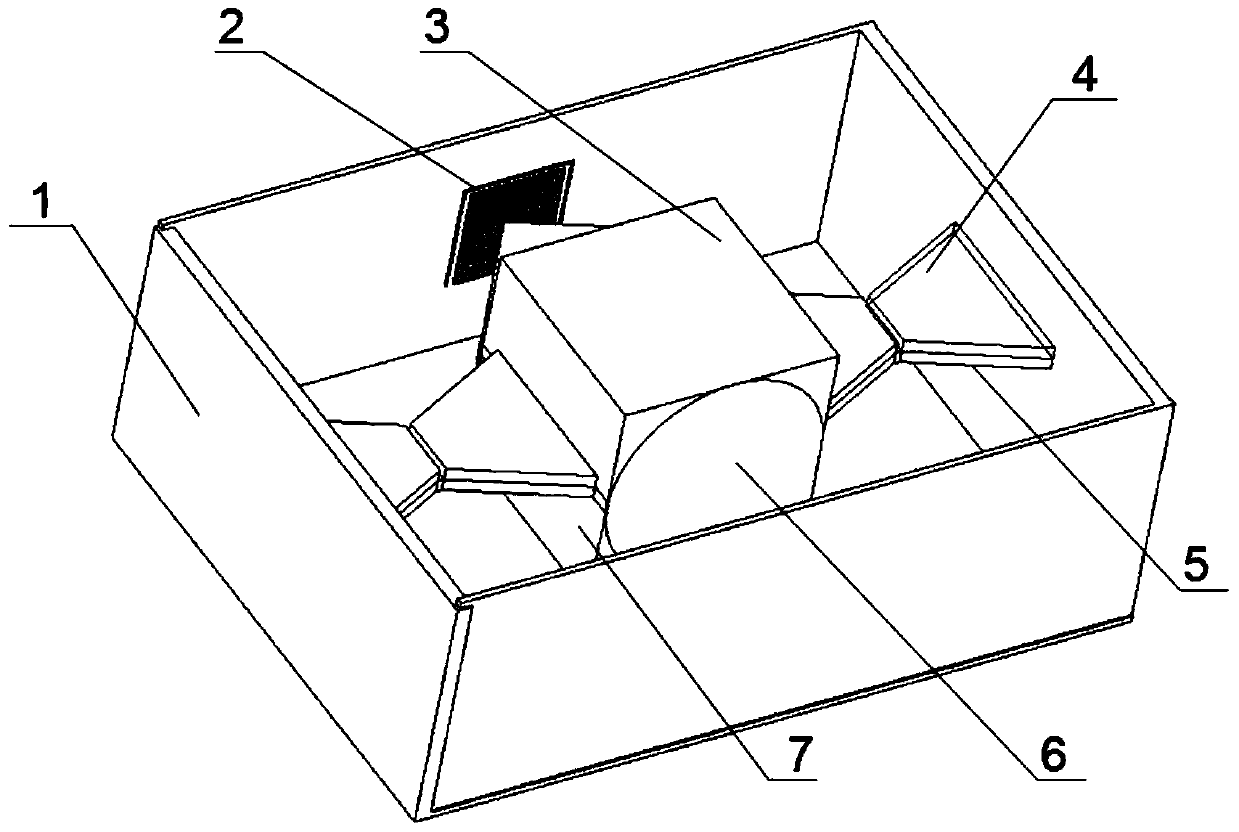
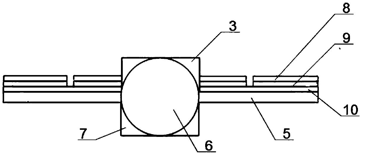
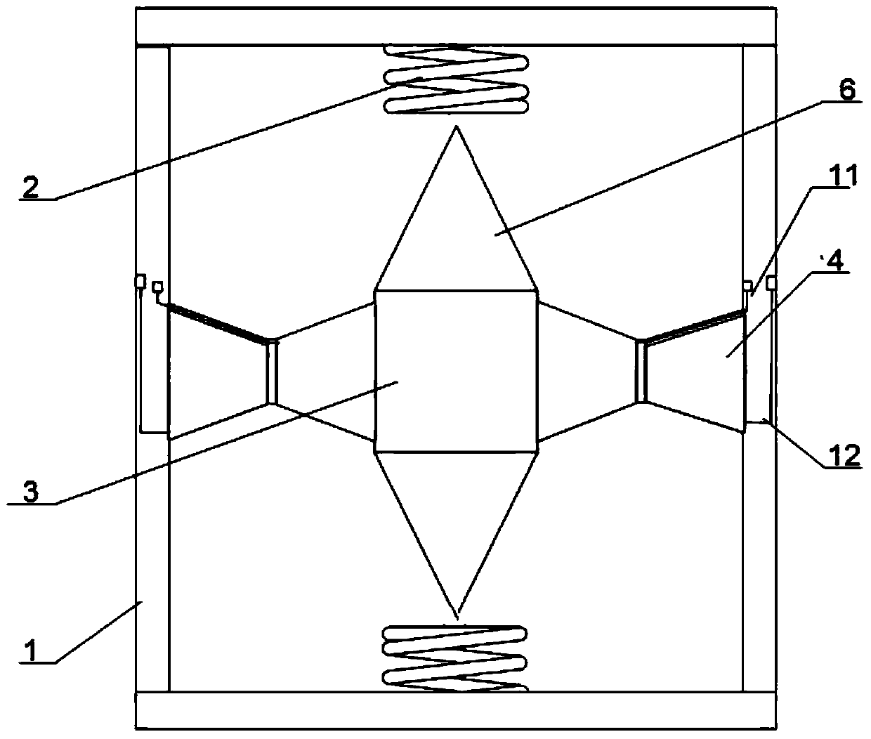
[0033] Such as figure 1 , 2 As shown in . , the lower permanent magnet 7, the upper electrode 8, the piezoelectric sheet 9, the lower electrode 10, the electrode lead wire 11 on the left piezoelectric sheet, and the electrode lead wire 12 on the right piezoelectric sheet. Coils 2 are symmetrically distributed on both sides of the inner wall of the housing 1, the coils 2 are perpendicular to the bottom surface of the housing 1, the coils 2 are fixedly connected to the housing 1, and the center of the coils 2 is vertically opposite to the tip of the tapered permanent magnet 6, and the coils 2 and There is a gap between the tip positions of the tapered permanent magnets 6 . The bottom of the tapered permanent magnet 6 is symmetrically fixed on the sides of the upper permanent magnet 3 and the lower permanent magnet 7 respectively, the middle part of the base beam 5 is sandwiched between the upper permanent magnet 3 and the lower permanent magnet 7, and the base beam 5 is vertic...


PUM


Abstract

The invention discloses a piezoelectric-electromagnetic compound energy accumulator and relates to piezoelectric-electromagnetic compound energy accumulator for improving an output power on the environment vibration condition, wherein the energy accumulator belongs to the technical field of the new energy and power generation. The energy accumulator is composed of a shell, coils, an upper permanent magnet, a piezoelectric ceramic material, a base beam, a conical permanent magnet, a lower permanent magnet, an upper electrode, a piezoelectric plate, a lower electrode, a left piezoelectric plate upper electrode lead, and a right piezoelectric plate upper electrode lead. A piezoelectric accumulation part and an electromagnetic accumulation part share the shell, the base beam, an upper permanent magnet, the lower permanent magnet, and the conical permanent magnet. According to the invention, the piezoelectric-electromagnetic compound energy accumulator has advantages of good green and pollution-free performances, large energy density, high reliability and environment adaptability, convenient operation and control, and low maintenance cost and the like. Problems of poor compatibility, low energy density, complex circuit connection, and inconvenient maintenance and the like of the conventional energy process can be solved. The piezoelectric-electromagnetic compound energy accumulator can be applied to energy supplying in a daily living vibration environment and severe environments of underground oil exploration and mining and the like and also can be used as an emergency standby power source.

Description

technical field [0001] The invention relates to a piezoelectric-electromagnetic composite energy harvester, in particular to a piezoelectric-electromagnetic composite energy harvester capable of increasing output power under environmental vibration conditions, and belongs to the technical field of new energy and power generation. Background technique [0002] Currently, known power supply elements are generally chemical batteries. The chemical battery has limited energy storage and needs to be replaced regularly, and the cost of manpower and material resources is high. [0003] The known measurement and control systems all need external power supply, and the external power supply and the sensor must be connected by wires, and the wiring is complicated and convenient; and it cannot be used in an environment without power supply or in an extremely harsh environment (such as the energy supply of an oil drilling drill bit positioning sensor). External power supply. [0004] Vi...

Claims


Application Information

Patent Timeline
IPC IPC(8): H02N2/18H02K35/00
CPCH02K35/00H02N2/186
Inventor 张广义高世桥刘海鹏武丽森董新博陈林雄
Owner BEIJING INSTITUTE OF TECHNOLOGYGY
Learn More