


Quick Research
Generate reliable direction feasibility study reports for your R&D in just a few steps.

Technical Q&A
Discover and master advanced knowledge NOW. Basics, ideas, possibilities, all at once.

Find Solutions
As an expert in R&D theories, this can generate solutions to your technical problems instantly.

Evaluate Feasibility
Analyze your overall solution with one click, know your potential R&D risks in advance.

Monitor Landscape
Get weekly tech updates, stay abreast of the latest tech innovations and key insights.
Computer power source
A computer power supply and circuit board technology, applied in computing, data processing power supply, electrical digital data processing and other directions, can solve the problem of poor heat dissipation effect of computer power supply, and achieve the enhancement of guiding effect and heat dissipation efficiency, reasonable design and simple structure. Effect
- Summary
- Abstract
- Description
- Claims
- Application Information
AI Technical Summary
Problems solved by technology
Method used
Image


Examples
Embodiment 1
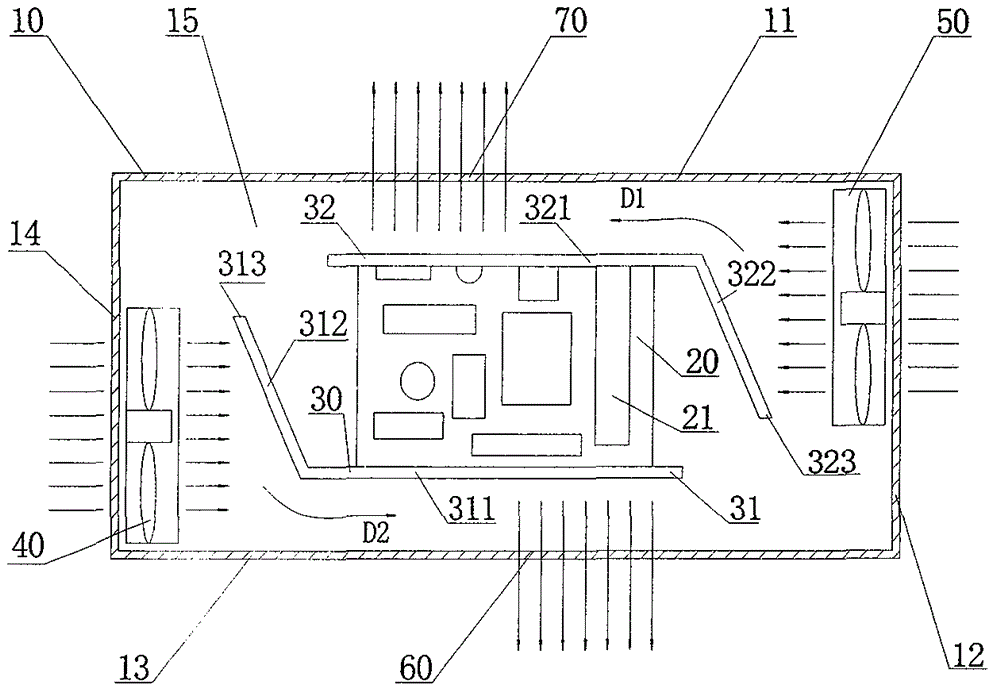
[0017] Such as figure 1 As shown, in Embodiment 1 of the present invention, the computer power supply includes a casing 10 , a circuit board 20 , a heat conducting plate 30 , a first fan 40 , a second fan 50 , a first air outlet 60 and a second air outlet 70 .
[0018] Such as figure 1 As shown, the housing 10 includes a first side wall 11 , a second side wall 12 , a third side wall 13 , a fourth side wall 14 and a bottom plate 15 . The circuit board 20 is arranged on the bottom plate 15, and the electronic components 21 required for the power supply of the computer are arranged on the circuit board 20. In this embodiment, the heat conduction plate 30 is arranged perpendicular to the bottom plate 15, the circuit board 20 includes a first side and a second side oppositely arranged, the heat conduction plate 30 includes a first heat conduction plate 31 and a second heat conduction plate 32, the first heat conduction plate 31 includes a first horizontal portion 311 and a first ...
Embodiment 2
[0022] Such as figure 2 As shown, in the second embodiment of the present invention, the heat conduction plate 30 also includes a third heat conduction plate 33, the third heat conduction plate 33 is arranged between the bottom plate 15 and the circuit board 20 and is in contact with the circuit board 20, the third heat conduction plate 33 They are respectively connected with the first heat conduction plate 31 and the second heat conduction plate 32 . The first floating end 313 extends a horizontal plane toward the first fan 40 , and the horizontal plane is parallel to the first horizontal portion 311 . The second floating end 323 extends a horizontal plane toward the second fan 50 , and the horizontal plane is parallel to the second horizontal portion 321 .
[0023] Such as figure 2 As shown, when the computer power supply is working, the circuit board 20 and the first fan 40 and the second fan 50 work simultaneously. Since the first inclined part 312 and the second incl...
PUM
 Abstract
Description
Claims
Application Information
 - R&D Engineer
- R&D Manager
- IP Professional
- Industry Leading Data Capabilities
- Powerful AI technology
- Patent DNA Extraction
Browse by: Latest US Patents, China's latest patents, Technical Efficacy Thesaurus, Application Domain, Technology Topic, Popular Technical Reports.
© 2024 PatSnap. All rights reserved.Legal|Privacy policy|Modern Slavery Act Transparency Statement|Sitemap|About US| Contact US: help@patsnap.com