
Mosfet-based low-field nuclear magnetic resonance q-switching circuit

A low-field nuclear magnetic resonance and conversion circuit technology, which is applied in the field of petroleum exploration, can solve the problems of low sensitivity of low-field nuclear magnetic resonance instruments, inaccurate detection of nuclear magnetic resonance signals, and long single-antenna recovery time constant. Single-antenna recovery time, shorten recovery time constant, and improve detection accuracy

Active Publication Date: 2018-06-22
CHINA UNIV OF PETROLEUM (BEIJING)
View PDF2 Cites 0 Cited by
  • Summary
  • Abstract
  • Description
  • Claims
  • Application Information

AI Technical Summary

Problems solved by technology

In order to improve the transmission efficiency of the signal and the signal-to-noise ratio level of the received signal, when designing a single antenna, it is required that the single antenna has a high quality factor Q value and a low antenna resonance frequency ω, but the recovery time constant of the single antenna and The single-antenna recovery time is proportional to the quality factor Q value and inversely proportional to the antenna resonance frequency ω, resulting in a long single-antenna recovery time constant and single-antenna recovery time
[0004] The longer single-antenna recovery time constant and the single-antenna recovery time will easily cause the nuclear magnetic resonance signal received by the single antenna to be covered by the energy discharge signal on the single antenna, resulting in inaccurate detection of the nuclear magnetic resonance signal by the low-field nuclear magnetic resonance instrument, and low Low sensitivity of field NMR instruments

Method used


Image

  • Mosfet-based low-field nuclear magnetic resonance q-switching circuit
  • Mosfet-based low-field nuclear magnetic resonance q-switching circuit
  • Mosfet-based low-field nuclear magnetic resonance q-switching circuit

Examples


Embodiment Construction

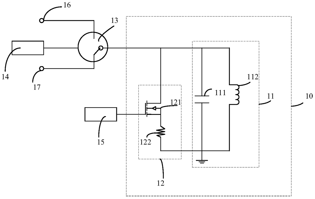
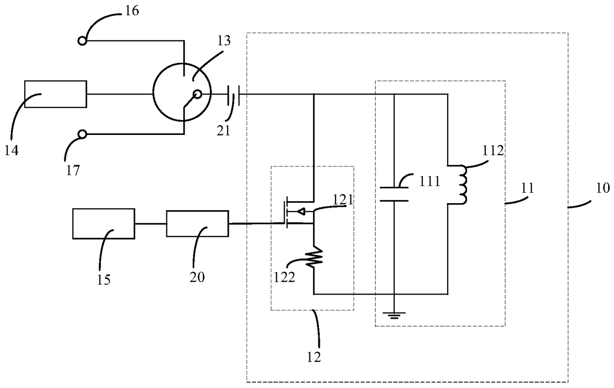
[0021] figure 1 It is a schematic diagram of a MOSFET-based low-field nuclear magnetic resonance Q conversion circuit provided by an embodiment of the present invention. The embodiment of the present invention provides a schematic diagram of a MOSFET-based low-field nuclear magnetic resonance Q conversion circuit for the long single-antenna recovery time constant and single-antenna recovery time in the prior art, such as figure 1 As shown, the MOSFET-based low-field nuclear magnetic resonance Q conversion circuit includes a resonant circuit 11, a conversion circuit 12, a duplexer 13, a first controller 14 and a second controller 15. Among them, the resonant circuit 11 includes a tuning capacitor 111 and an inductor. 112, the tuning capacitor 111 and the inductor 112 are connected in parallel; the conversion circuit 12 includes a MOSFET circuit 121 and a power resistor 122, the MOSFET circuit 121 and the power resistor 122 are connected in series, the conversion circuit 12 and the...


PUM


Abstract

The invention provides an MOSFET-based low-field nuclear magnetic resonance Q converting circuit. The converting circuit comprises a resonance circuit, a converting circuit, a duplexer, a first controller and a second controller. The resonance circuit comprises a tuning capacitor and an inductor which is parallel connected with the tuning capacitor. The converting circuit comprises an MOSFET circuit and a power resistor which is serially connected with the MOSFET circuit. The converting circuit is parallel connected with the resonance circuit so that a parallel network is formed. The duplexer is serially connected with the parallel network. The first controller is connected with the duplexer. The second controller is connected with the MOSFET circuit. By controlling on or off of the MOSFET circuit, a single antenna is allowed to work in a high Q-value state when a radio frequency signal is sent and a nuclear magnetic resonance signal is received, and during discharging of energy of the resonance circuit, the signal antenna works in a low Q-value state, so restoration time constant and restoration time of the single antenna are reduced, and detection precision for the nuclear magnetic resonance signal by the low-field nuclear magnetic resonance device and sensitivity of the nuclear magnetic resonance device are improved.

Description

Technical field [0001] The embodiment of the present invention relates to the field of petroleum exploration, in particular to a low-field nuclear magnetic resonance Q conversion circuit based on MOSFET. Background technique [0002] Nuclear magnetic resonance logging is a new logging technology suitable for open hole wells. It is currently the only logging method that can directly measure the flow characteristics of free fluid in arbitrary lithological reservoirs, and has obvious advantages. Nuclear magnetic resonance technology uses the paramagnetism of atomic nuclei and the external magnetic field that interacts with them. [0003] The existing low-field nuclear magnetic resonance instrument adopts a single antenna structure. A single antenna emits a high-power radio frequency signal to excite the measured sample, and a single antenna is used to receive the nuclear magnetic resonance signal generated on the measured sample at a specific time. It can complete the function of rec...

Claims


Application Information

Patent Timeline
Patent Type & Authority Patents(China)
IPC IPC(8): G01V3/32
Inventor 肖立志冯硕朱明达杨光廖广志
Owner CHINA UNIV OF PETROLEUM (BEIJING)
Learn More