
Method for designing continuous phase-modulation signal of non-continuous spectrum

A technology of phase modulation signal and design method, applied in the direction of reflection/re-radiation of radio waves, utilization of re-radiation, measurement device, etc., can solve the details of pass-stop band, signal design can not match, signal-to-interference ratio and side lobe indicators The proportion is weighed against the problems of inflexible design, etc., to achieve better real-time performance, improved signal-to-interference ratio, and time-saving effects.

Active Publication Date: 2015-12-09
HARBIN INST OF TECH
View PDF2 Cites 6 Cited by
  • Summary
  • Abstract
  • Description
  • Claims
  • Application Information

AI Technical Summary

Problems solved by technology

[0004] In order to solve the problem that the current waveform design method does not consider the details of each frequency point of each pass-stop band, the signal cannot be fully matched with the changeable interference environment during signal design and the signal-to-interference ratio in the design process The problem that the design of the proportion trade-off between the side lobe index and the side lobe index is not flexible enough

Method used

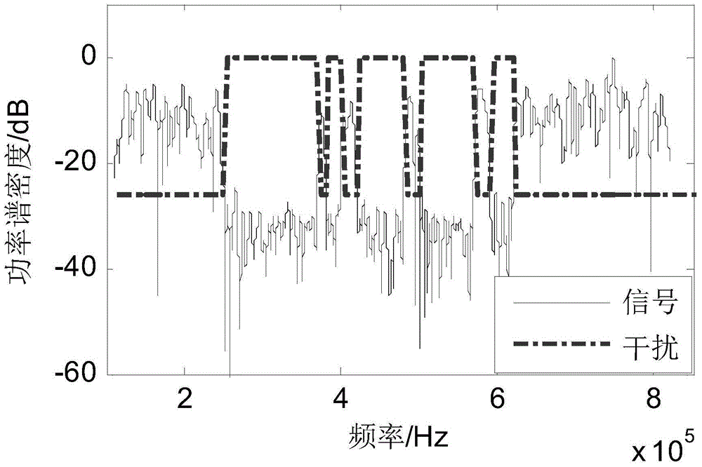
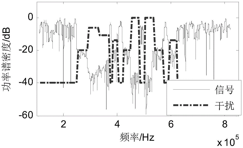
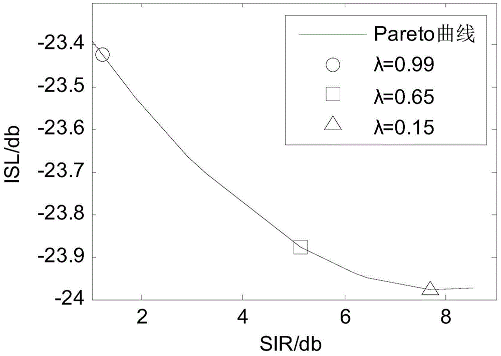

Image

  • Method for designing continuous phase-modulation signal of non-continuous spectrum
  • Method for designing continuous phase-modulation signal of non-continuous spectrum
  • Method for designing continuous phase-modulation signal of non-continuous spectrum

Examples


specific Embodiment approach 1

[0034] A discontinuous spectrum continuous phase modulation signal design method, comprising the following steps:

[0035] Step 1. Set the form of the discrete signal in the single pulse after sampling as

[0036] x=[x 1 ; x 2 ;...;x N ](1)

[0037] Among them, N is the sequence length;

[0038] Since the variable-mode signal will make it difficult for the transmitter amplifier to work in a saturated state all the time, it will have an impact on the power range and signal-to-noise ratio of the transmitted signal. Therefore, a constant-mode signal is generally used. Under the assumption of unit transmitted energy, the signal form is determined by the phase Decision; the nth sample value x of the signal n Expressed as

[0039] x n = e jΨ n - - - ( 2 )

[0040] A...

specific Embodiment approach 2

[0055] The process of designing the overall objective function in step 2 of the present embodiment is as follows:

[0056] Step 2.1, the signal-to-interference ratio (SIR) objective function of the design signal x is

[0057] P SIR =x H Kx(6)

[0058] Step 2.2, the distance side lobe objective function of the design signal x is

[0059] P ACF =2N-x H b-b H x(7)

[0060] Step 2.3, the total objective function of the design signal x is

[0061] P Total =λP SIR +(1-λ)P ACF (8).

[0062] =λx H Kx+(1-λ)(2N-x H b-b H x)

[0063] Other steps and parameters are the same as those in the first embodiment.

specific Embodiment approach 3

[0064] The process of step 2.1 designing the signal-to-interference ratio (SIR) objective function of the present embodiment is as follows:

[0065] Signal-to-interference ratio r of signal x s / n The analytical expression of

[0066] r s / n = P s P n = | ∫ - ∞ + ∞ H ( f ) X ( f ) e j 2 πft 0 ...


PUM


Abstract

The invention relates to a method for designing a signal, specifically to a method for designing a continuous phase-modulation signal of a non-continuous spectrum, and aims to solve the problem in an existing waveform design method that details of each frequency point of each pass band and stop band are not considered, so sufficient matching with changeable interference environment cannot be realized in signal design and the problem that balance design of a proportion of a signal to interference ratio to a sidelobe index is not flexible enough in a design process. The method firstly directs at a signal design general objective function P<Total>=[lambda]x<H>kx+(1-lambda)(2N-x<H>b-b<H>x), then utilizes a gradient iteration method to obtain a waveform optimal solution; then weight lambda is traversed from 1 to 0, a series of values of the signal to interference ratio and the sidelobe are obtained, one of the indexes are used as a horizontal axis, the other index is used as a longitudinal axis, and a curve that is obtained is a Pareto optimal curve; and the Pareto optimal curve is used as a tool for assisting selection an optimal balance between objective functions in multi-objective optimization to design the continuous phase-modulation signal of the non-continuous spectrum. The method provided by the invention is suitable for design of the continuous phase-modulation signal of the non-continuous spectrum.

Description

technical field [0001] The invention relates to a signal design method. Background technique [0002] Radar signal design plays a vital role in the radar system, and its echo contains a large amount of target information, including spatial position, movement and so on. The frequency band where the radar operating frequency is located often has serious narrow-band interference, and the interference has time-varying characteristics. The use of sparse frequency signals can avoid interference frequency bands, and the transmission energy is allocated to discrete "quiet" frequency bands to obtain a large signal-to-interference-noise ratio. However, the sparsity of the spectrum will cause the elevation of the range sidelobe, and it is prone to adverse situations such as the strong target sidelobe submerging the weak target main lobe, thus affecting the detection of the target. Since the signal-to-interference-noise ratio and the range sidelobe are coupled in a conflicting form, t...

Claims


Application Information

Patent Timeline
Patent Type & Authority Applications(China)
IPC IPC(8): G01S13/88
CPCG01S13/88
Inventor 位寅生尚进
Owner HARBIN INST OF TECH
Learn More