
Grounding grid breakpoint diagnostic method based on transient electromagnetic abnormal ring principle

A diagnostic method and transient electromagnetic technology, applied in the fault location and other directions, can solve problems such as blindness, power failure, and excavation, and achieve the effect of reducing complexity.

Active Publication Date: 2015-12-09
JILIN UNIV
View PDF6 Cites 18 Cited by
  • Summary
  • Abstract
  • Description
  • Claims
  • Application Information

AI Technical Summary

Problems solved by technology

[0005] The technical problem to be solved by the present invention is to provide a grounding grid breakpoint diagnosis method that overcomes the problems of excavation, power failure, blindness, and grounding lead restrictions, and provides a grounding system based on the theory of transient electromagnetic anomalies. Network Breakpoint Diagnosis Method

Method used


Image

  • Grounding grid breakpoint diagnostic method based on transient electromagnetic abnormal ring principle
  • Grounding grid breakpoint diagnostic method based on transient electromagnetic abnormal ring principle
  • Grounding grid breakpoint diagnostic method based on transient electromagnetic abnormal ring principle

Examples


Embodiment Construction

[0039] In order to make the object, technical solution and advantages of the present invention more clear, the present invention will be further described in detail below in conjunction with the examples. It should be understood that the specific embodiments described here are only used to explain the present invention, not to limit the present invention.

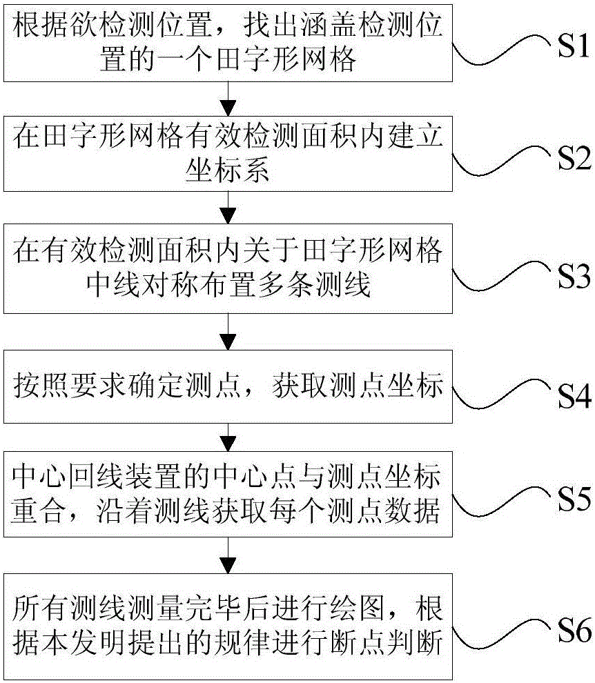
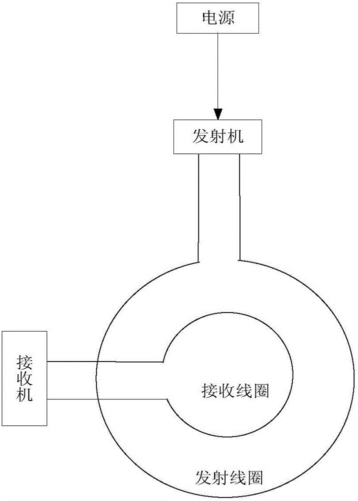
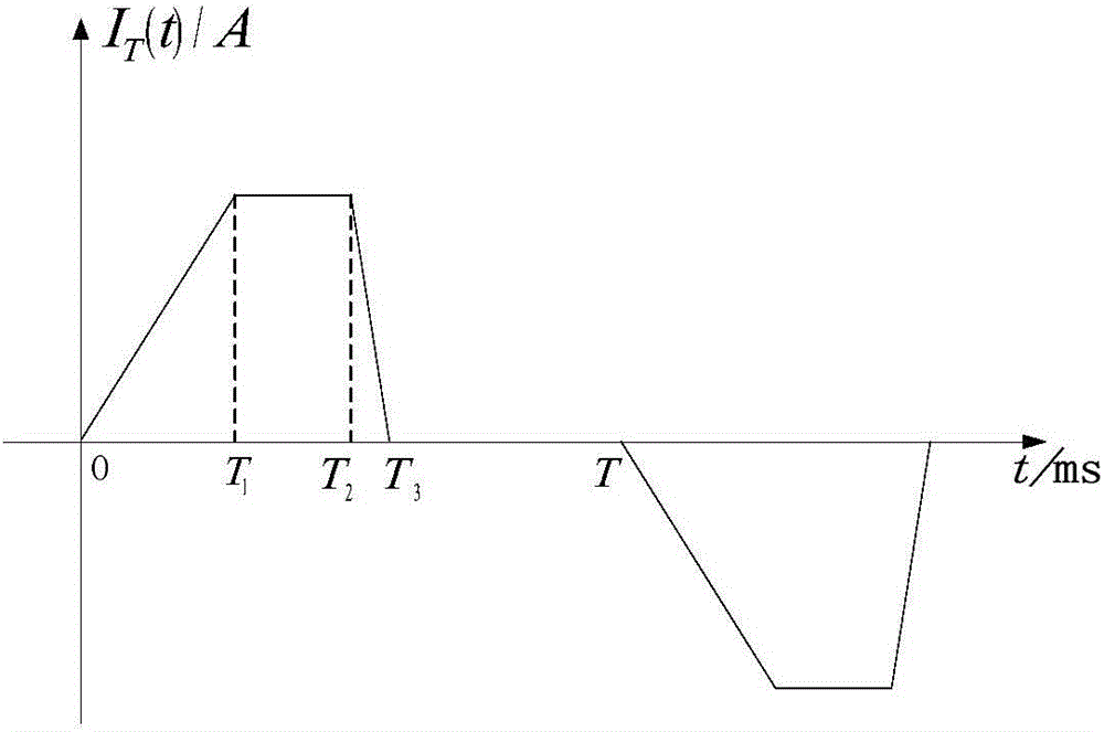
[0040] see figure 1 It is a flow chart of a grounding grid breakpoint diagnosis method disclosed in an embodiment of the present invention. figure 2 It is a structural schematic diagram of the transient electromagnetic detection device in the embodiment of the present invention. The device includes a transmitting coil and a receiving coil, wherein the transmitting coil is connected with the transmitter, the power supply supplies power to the transmitter, and the receiving coil is connected with the receiver. The center points of the transmitting coil and receiving coil coincide. Transient electromagnetic transmitting co...


PUM


Abstract

The invention discloses a grounding grid breakpoint diagnostic method based on a transient electromagnetic abnormal ring principle. The method comprises the steps of: according to a position to be detected, finding out one grid in the shape of a Chinese character 'tian' which covers the detected position; establishing a coordinate system in an effective detection area above the tian-shaped grid; placing a plurality of detecting lines in the effective detection area, and requiring the detecting lines to be symmetrical about the middle lines of the tian-shaped grid; determining coordinates of detecting points on each detecting line, and requiring consistency between the intervals of all the detecting points of the detecting lines and the positions of the detecting points; adopting a center loop device to coincide central points of emitting coils with receiving coils and the detecting points, carrying out measurement along one detecting line point by point, and obtaining measurement data; and drawing a secondary sensing voltage map of different detecting points of each detecting line at different sampling moments, and judging the positions breakpoints according to the rules of the breakpoints existing at different positions of the tian-shaped grounding grid. By adopting the method, the breakpoint diagnose can be directly carried out by means of the measured secondary sensing voltages under that condition that the normal operation of a power system is ensured.

Description

technical field [0001] The invention discloses a grounding grid breakpoint diagnosis method based on the principle of transient electromagnetic abnormal loop. More specifically, it can ensure that the breakpoint diagnosis is directly performed by the measured secondary induced voltage value under the normal operation of the power system. Background technique [0002] The grounding grid of power generation and substations is an important measure to ensure the safe and reliable operation of the power system, and its reliability is directly related to the safe operation of the power grid. Once the grounding grid fails, it will cause incalculable losses to equipment, power supply and people's life and property safety. Diagnosing the defects of the grounding grid is of great practical significance to ensure the safe and reliable operation of the power system and the safety of equipment and operators. It has become an important measure to prevent accidents in the power sector. ...

Claims


Application Information

Patent Timeline
IPC IPC(8): G01R31/08
Inventor 栾卉嵇艳鞠郑建波董冠良于生宝刘南南
Owner JILIN UNIV
Learn More