
Particle chain shock absorber and particle chain damping measuring method

A shock-absorbing damping and testing method technology, applied in the field of shock-absorbing dampers, can solve problems such as the narrow shock-absorbing frequency band of liquid dampers, and achieve the effects of obvious shock-absorbing effect, easy maintenance, and easy dissipation efficiency.

Inactive Publication Date: 2015-12-09
BEIJING INSTITUTE OF TECHNOLOGYGY
View PDF13 Cites 3 Cited by
  • Summary
  • Abstract
  • Description
  • Claims
  • Application Information

AI Technical Summary

Problems solved by technology

[0002] The liquid damper that exists in real life uses the inertial and viscous energy dissipation of the liquid in a fixed container to reduce the vibration of the structure, but the liquid damper has the problem of a narrow damping frequency band

Method used


Image

  • Particle chain shock absorber and particle chain damping measuring method
  • Particle chain shock absorber and particle chain damping measuring method
  • Particle chain shock absorber and particle chain damping measuring method

Examples


Embodiment 1

[0038] To protect the descent landing gear, it is necessary to attenuate the shock as much as possible. For example, the landing of an aerospace probe is achieved through structural design and impact attenuation devices to achieve a safe landing. Because the granular material can pass through friction and inelastic collision between particles, it has good energy dissipation capacity and can play a certain shock absorption effect. Therefore, Embodiment 1 of the present invention provides a particle chain shock-absorbing damping device 1.

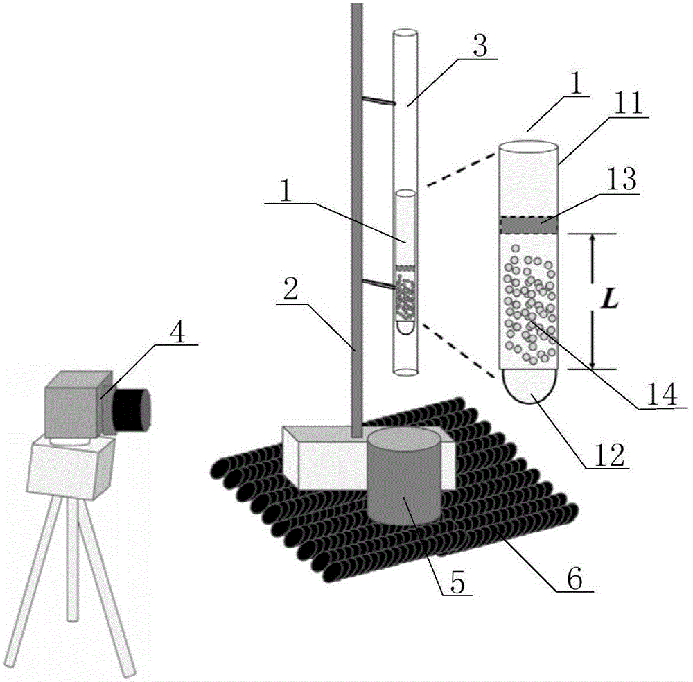
[0039] figure 1 It is a schematic structural view of the test method of the particle chain shock absorbing and damping device of the present invention, figure 2 It is a structural schematic diagram of the granular chain shock-absorbing damping device of the present invention. Such as figure 1 and figure 2 As shown, the particle chain damping device 1 includes: a hollow cylinder 11 , an acrylic glass ball 12 , a baffle 13 and a pluralit...

Embodiment 2

[0050] This embodiment provides a particle chain shock absorption and damping test method, which test method includes the following steps:

[0051] (a), the acrylic glass ball 12 is embedded in the bottom of the hollow cylinder 11, and then a plurality of particle chains 14 are placed on the lower surface of the hollow cylinder 11 in a spiral initial placement state, each particle chain Including at least 8 particles, and finally the baffle plate 13 is detachably fixed on the upper part of the hollow cylinder 11, finally forming the particle chain shock-absorbing damping device 1;

[0052] (b), place the fixed bracket 2 on the level ground to fix the smooth glass conduit 3, the smooth glass conduit 3 is a conduit with upper and lower openings, its radius is slightly larger than the radius of the hollow cylinder 11, and the particle chain shock-absorbing damping device 1 Placed inside the smooth glass conduit 3. Among them, the purpose of the smooth glass conduit 3 is to guide...


PUM


Abstract

The invention discloses a particle chain shock absorber. The shock absorber comprises a hollow cylinder, acrylic glass balls, a baffle plate and multiple particle chains. The acrylic glass balls are embedded in the bottom of the hollow cylinder and used for reducing vibration strength and preventing the particle chains from falling off from the bottom of the hollow cylinder. The baffle plate is arranged on the upper part of the hollow cylinder. The particle chains are arranged in the hollow cylinder. Each of the particle chains comprises at least eight particles and is initially placed on the lower surface of the interior of the hollow cylinder in a screw type manner. The invention also provides a particle chain damping measuring method. The shock absorber produces obvious damping effects, and is simple and firm in structure, easy to maintain and capable of working in very wide range of humidity and temperature and vibration frequency, and dissipation power can be easily adjusted. The damping measuring method tests the damping effects of the shock absorber.

Description

technical field [0001] The invention relates to the field of shock absorbing dampers, in particular to a particle chain shock absorbing and damping device and a particle chain shock absorbing and damping testing method thereof. Background technique [0002] The liquid damper that exists in real life uses the inertial and viscous energy dissipation of the liquid in a fixed container to reduce the vibration of the structure, but the liquid damper has the problem of a narrow damping frequency band. [0003] Therefore, there is an urgent need in this field for a shock-absorbing damper with a wider shock-absorbing frequency band, a wider application range and an obvious shock-absorbing effect. Contents of the invention [0004] The embodiment of the present invention aims to overcome the above technical problems, and proposes a particle chain shock-absorbing damping device and its particle chain with simple structure, wide shock-absorbing frequency band, insensitive to containe...

Claims


Application Information

Patent Timeline
IPC IPC(8): G01M13/00F16F7/01
Inventor 郑宁许程史庆藩
Owner BEIJING INSTITUTE OF TECHNOLOGYGY
Learn More