
Flue gas waste heat utilization system

A flue gas waste heat and flue gas technology, applied in lighting and heating equipment, combustion methods, indirect carbon dioxide emission reduction, etc., can solve the problems of wasting waste heat resources and low efficiency of waste heat utilization, and improve the effect of dust removal

Active Publication Date: 2017-10-10
ELECTRIC POWER RES INST OF STATE GRID ZHEJIANG ELECTRIC POWER COMAPNY +3
View PDF10 Cites 0 Cited by
  • Summary
  • Abstract
  • Description
  • Claims
  • Application Information

AI Technical Summary

Problems solved by technology

[0003] At present, the recovered heat is mainly recovered through the low-pressure heat recovery system of the steam turbine. This kind of recovery can achieve a certain energy-saving effect by squeezing the steam turbine to extract steam. However, this method does not have a high utilization efficiency for the above-mentioned waste heat and wastes A large number of waste heat resources

Method used


Image

  • Flue gas waste heat utilization system

Examples


Embodiment Construction

[0024] The following will clearly and completely describe the technical solutions in the embodiments of the present invention with reference to the accompanying drawings in the embodiments of the present invention. Obviously, the described embodiments are only some, not all, embodiments of the present invention. Based on the embodiments of the present invention, all other embodiments obtained by persons of ordinary skill in the art without making creative efforts belong to the protection scope of the present invention.

[0025] The core of the present invention is to provide a flue gas waste heat utilization system, which can improve the utilization efficiency of flue gas waste heat.

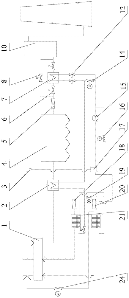
[0026] Please refer to figure 1 , figure 1 It is a schematic structural diagram of a specific embodiment provided by the present invention.

[0027] In the specific embodiment provided by the present invention, the air preheater is connected to the high-temperature flue gas cooler 2, the high-...


PUM


Abstract

The invention discloses a smoke waste heat utilization system. The system comprises an air preheater, wherein the air preheater is connected with a high-temperature smoke cooler, the high-temperature smoke cooler is connected with a dust removal device, the dust removal device is connected with a desulfurizing device, a low-temperature smoke cooler is further connected between the dust removal device and the desulfurizing device, a heating medium channel of the high-temperature smoke cooler and a heating medium channel of the low-temperature smoke cooler are both connected with a heat exchange device used for heating air supplied to the air preheater, and the heat exchange device is a heat-pipe type heat exchanger. The system can recover smoke waste heat between the air preheater and the dust removal device, can also recover smoke waste heat between the dust removal device and the desulfurizing device and can transfer recovered heat to the air supplied to the air preheater through the heat exchange device, then the heat is recovered to a thermal system of a boiler, and the utilization efficiency of the smoke waste heat of the boiler is greatly improved.

Description

technical field [0001] The invention relates to the technical field of waste heat recovery and utilization, in particular to a flue gas waste heat utilization system. Background technique [0002] The actual flue gas temperature at the outlet of the rotary air preheater used in large coal-fired units is about 125°C, while for the low-temperature electrostatic precipitator connected after the air preheater, it is usually required that the flue gas temperature at the inlet should meet 80°C °C to 90 °C. Therefore, in the wind and smoke system of the boiler, devices such as a flue gas cooler can be installed to cool the flue gas as needed, and at the same time recover the waste heat of the flue gas. [0003] At present, the recovered heat is mainly recovered through the low-pressure heat recovery system of the steam turbine. This kind of recovery can achieve a certain energy-saving effect by squeezing the steam turbine to extract steam. However, this method does not have a high...

Claims


Application Information

Patent Timeline
Patent Type & Authority Patents(China)
IPC IPC(8): F23L15/00F23J15/02
CPCY02E20/34
Inventor 吕洪坤张明熊建国李凤瑞
Owner ELECTRIC POWER RES INST OF STATE GRID ZHEJIANG ELECTRIC POWER COMAPNY
Learn More