Clamping pliers device and method for using same

A technology of punching pliers and pliers, which is applied in earthwork drilling, drilling equipment, drill pipes, etc., and can solve problems such as complex on-site maintenance, failure of clamping cylinder seals, failure of cylinder rods and seals, etc.

Active Publication Date: 2015-12-09
BEIJING JJC PETROLEUM EQUIP CO LTD
View PDF6 Cites 7 Cited by
  • Summary
  • Abstract
  • Description
  • Claims
  • Application Information

AI Technical Summary

Problems solved by technology

[0004] There are the following disadvantages in the existing punching tongs device: one, due to the relatively large torque load of the make-up and breakout of the drilling tool, a pair of large-caliber clamping cylinders are needed to generate a large clamping force (usually not less than 100 tons), so that the The pincer teeth are embedded in the outer wall of the drill tool joint to prevent slippage during punching and buckling operations; second, because the load of making and breaking out is often an impact load, and it is perpendicular to the clamping cylinder rod, it is easy to cause the seal of the clamping cylinder to fail; The surface usually has mud, and the mud is in direct contact with the cylinder rod of the clamping cylinder, which may also easily cause the failure of the cylinder rod and the seal; 4. Since the make-up and break-out torque operations are different between different drill joints, the punching tongs The clamping force is always set at the required value at the maximum torque load, which causes excessive bite on the tool joint
In a word, the existing punching pliers device has short working life, complex on-site maintenance, shortened drilling tool life and other shortcomings and deficiencies

Method used


Image

  • Clamping pliers device and method for using same
  • Clamping pliers device and method for using same
  • Clamping pliers device and method for using same

Examples


Embodiment Construction

[0035] The preferred embodiments of the present invention will be described below with reference to the accompanying drawings.

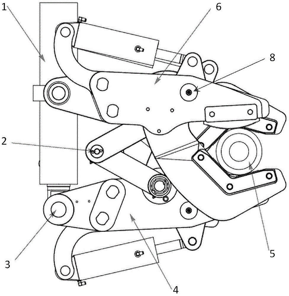
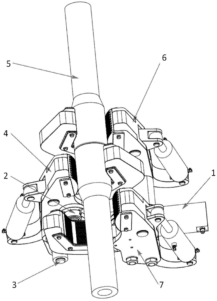
[0036] figure 1 with figure 2 A top schematic view and a perspective schematic view of a punch clamp device according to an embodiment of the present invention are respectively shown. As shown in the figure, the punch clamp device includes an upper pliers 6, a lower pliers 7, and a middle pliers 4 installed between the upper pliers and the lower pliers. The punching pliers device also includes two sets of connecting structures 2 which are installed between the lower pliers 7 and the middle pliers 4 and between the middle pliers 4 and the upper pliers 6 respectively.

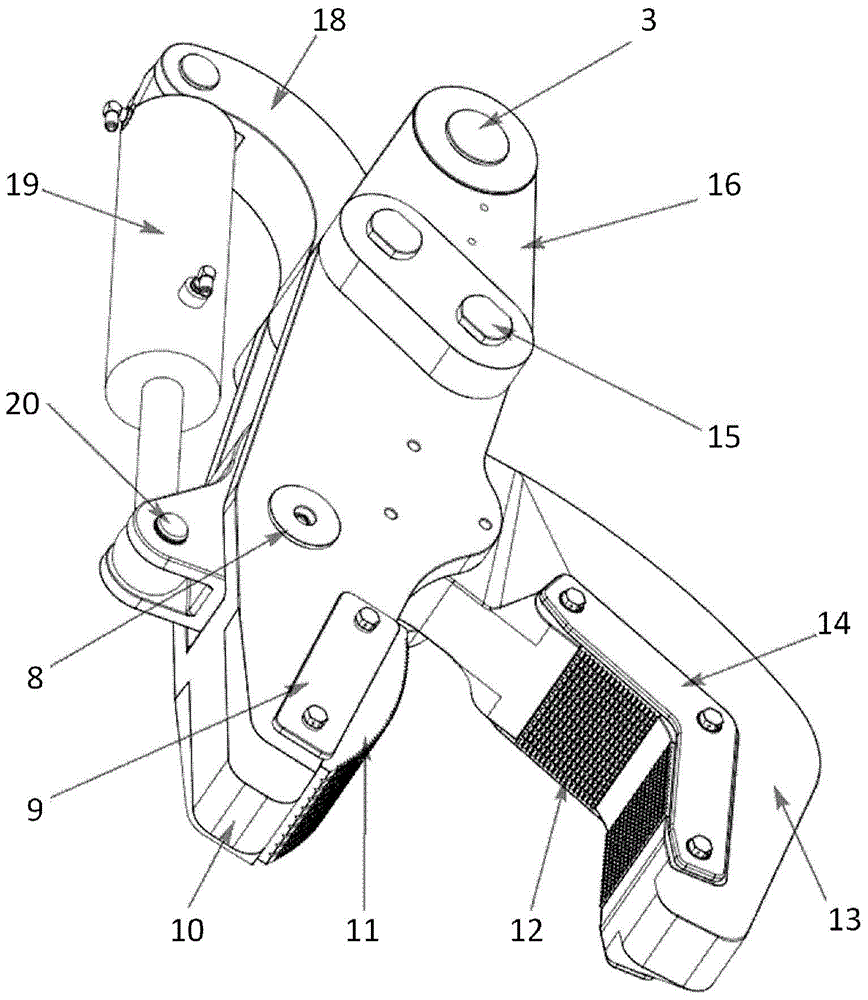
[0037] image 3 A perspective schematic diagram of the middle pliers of the punch pliers device according to an embodiment of the present invention is shown. As shown in the figure, the middle pliers 4 includes a pliers body, the pliers body includes: a pliers head body, the pliers head bo...


PUM


Abstract

The embodiment of the present invention discloses a clamping pliers device which comprises an upper pliers piece, a lower pliers piece and a central pliers piece installed between the upper pliers piece and lower pliers piece, wherein the upper pliers piece and the lower pliers piece are configured into a driller joint which rotates in the first direction, and the central pliers piece is configured into another driller joint which rotates on a second direction opposite to the first direction. Or, the upper pliers piece and the lower pliers piece are configured to fix one driller joint, and the central pliers piece is configured to rotate another driller joint. Or, the upper pliers piece and the lower pliers piece are configured to rotate the drill joint, and the central pliers piece is configured to fix another driller joint. The invention further discloses a method for using the clamping pliers device.

Description

Technical field [0001] The invention relates to a machine for petroleum drilling, in particular to a punching tong device for providing buckling and breaking operations for drilling tool connection and a method for using the buckling tong device to perform drilling tool buckling and shackle operations. Background technique [0002] With the improvement of the automation level of oil drilling operations, wellhead hydraulic oil tools with a high degree of automation (such as power drill pipe tongs, power sleeve tongs, iron drillers, etc.) are more and more widely used. Due to the harsh working environment for the make-up and shackle operations of the drilling tool, the equipment directly contacts the chemical mud and bears large torque loads and often has impact loads. It is necessary to have a more durable, easy-to-maintain, simple structure A punching pliers device and method for buckling and shackle operations. [0003] At present, the hydraulic punching pliers device used for th...

Claims


Application Information

Patent Timeline
Patent Type & Authority Applications(China)
IPC IPC(8): E21B19/18
CPCE21B19/163
Inventor 李学军刘忱崔杰
Owner BEIJING JJC PETROLEUM EQUIP CO LTD
Why Eureka
Try Eureka