Eureka AIR delivers breakthrough ideas for toughest innovation challenges, trusted by R&D personnel around the world.

Flood prevention baffle and working method thereof

A technology of block and water bag, applied in the direction of rain/wind shutters, buildings, building components, etc., can solve the problems of improper installation of sealing strips, easy leakage of water at hinges, and easy to be washed out of water blocking devices, so as to achieve the sealing effect. Good, cost saving, convenient transportation effect

Active Publication Date: 2015-12-09
JIANGSU ELECTRIC POWER CO +3
View PDF5 Cites 4 Cited by
  • Summary
  • Abstract
  • Description
  • Claims
  • Application Information

AI Technical Summary

Problems solved by technology

[0002] At present, some protected objects such as underground substations and power distribution rooms that have been built for many years, use bricks or concrete to build fixed water barriers. The big disadvantage is that it is extremely inconvenient for large-scale equipment to enter and exit.
[0003] The State Intellectual Property Office published a utility model patent (application number CN2009200617650) on May 5, 2010. This patent discloses a flood-proof and water-retaining device, which uses multiple waterproof units connected to each other to achieve the purpose of waterproofing. Its large The disadvantage is that the structure of the flood control water retaining device is complicated; the waterproof unit has a built-in water bag, and if the water bag is not heavy enough when the flood comes, the water retaining device is easily washed away
[0004] The State Intellectual Property Office disclosed a utility model patent (application number CN2009202743380) on 2010-11-24, which discloses a movable flood control baffle device, which uses at least two left and right water baffles and sealing strips hinged together in sequence To achieve the purpose of waterproofing, the biggest disadvantage is that the sealing strip is not installed in place, the hinges are prone to water leakage, and the waterproof effect is not good.

Method used


Image

  • Flood prevention baffle and working method thereof
  • Flood prevention baffle and working method thereof
  • Flood prevention baffle and working method thereof

Examples


Embodiment Construction

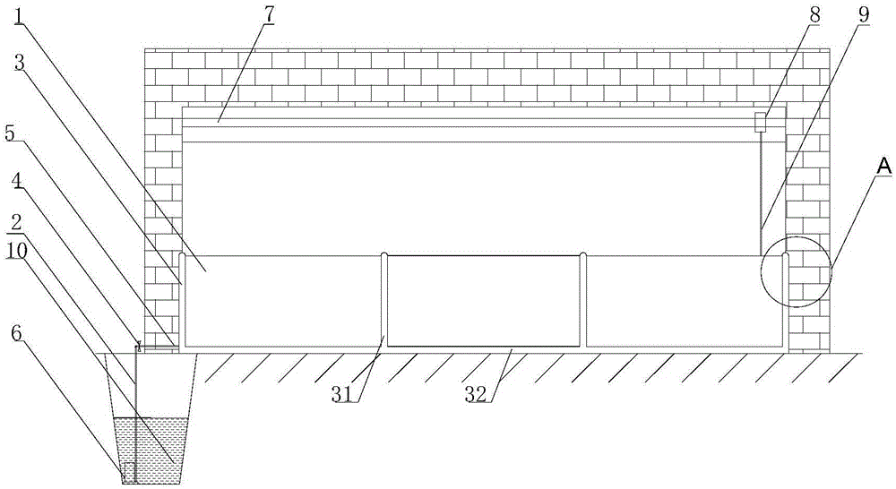
[0024] The present invention will be described in detail below in conjunction with the accompanying drawings. The present invention includes a block 1, a pipeline 2, a telescopic water bag 3, a valve 4, a hard water outlet 5, a high-pressure water delivery pump 6, a slide rail 7, a slider 8, and a connecting rod 9 and water source 10.

[0025] Protected objects such as substations and power distribution rooms are provided with doors 11 for accessing operations, and the flood control baffle is arranged at the bottom of the door 11; The flood control baffle includes several blocks 1, pipes 2, telescopic water bags 3, valves 4, hard water outlets 5, high-pressure water delivery pumps 6, slide rails 7, sliders 8, connecting rods 9 and water sources 10; upright water bags 31 and the bottom edge water bag 32 jointly constitute the telescopic water bag 3, and the upright water bags 31 are connected between several block blocks 1; the bottom edge water bag is provided at the bottom of...


PUM


Abstract

The invention discloses a flood prevention baffle and a working method thereof and relates to flood prevention devices. The flood prevention baffle is simple and firm in structure and good in sealing effect. The baffle comprises two or more stop blocks, flexible water bags, a hard water outlet, a pipeline, a water pump, a valve guide device and a water source. The flood prevention baffle has the advantages that in case of flood attack, the baffle can be accurately unfolded to stop flood and be folded and put away after the flood steps back, and other work is not affected; the baffle is constituted by the two or more stop blocks and the flexible water bags, and the structure is simple; the height of the baffle is 50-120 cm, and the baffle is small in size and convenient to transport; the stop blocks are connected through stand water bags, bottom edge water bags are arranged at the bottom edges of the stop blocks, and the total sealing effect is good; the guide device is adopted, and the baffle can be unfolded rapidly; the guide device further plays the function of reinforcing the flood prevention baffle, so that the flood prevention baffle is not prone to being shattered through flushing; the stand water bags and the bottom edge water bags are utilized for sealing spaces between the baffle and a wall and the ground, no additional sealing strip is needed, and the cost is saved.

Description

technical field [0001] The invention relates to a flood control device, in particular to a flood control baffle and a working method thereof. Background technique [0002] At present, some protected objects such as substations and power distribution rooms that have been built for many years underground and on low terrain use bricks or concrete to build fixed water-retaining barriers. The big disadvantage is that it is extremely inconvenient for large-scale equipment to enter and exit . [0003] The State Intellectual Property Office published a utility model patent (application number CN2009200617650) on May 5, 2010. This patent discloses a flood-proof and water-retaining device, which uses multiple waterproof units connected to each other to achieve waterproofing. Its large The disadvantage is that the structure of the flood control water retaining device is complicated; the waterproof unit has a built-in water bag, and if the water bag is not heavy enough when the flood c...

Claims


Application Information

Patent Timeline
Patent Type & Authority Applications(China)
IPC IPC(8): E06B7/26E06B5/02
Inventor 孙国娣陆子俊高晓宁王梦超尹鲁兵
Owner JIANGSU ELECTRIC POWER CO
Why Eureka
Eureka Blog
Learn More