
Double air chamber heated urea catalytic hydrolysis reactor and method

A urea catalytic hydrolysis and reactor technology, which is applied in the field of urea catalytic hydrolysis reactor heated by double chambers, can solve the problems of difficult cleaning, high urea purity requirements, and no consideration of impurity treatment, etc.

Active Publication Date: 2015-12-09
DATANG ENVIRONMENT IND GRP +1
View PDF4 Cites 1 Cited by
  • Summary
  • Abstract
  • Description
  • Claims
  • Application Information

AI Technical Summary

Problems solved by technology

However, the existing urea catalytic hydrolysis equipment does not consider the treatment of impurities, it is difficult to clean up, and it requires high purity of urea, which increases the operating cost

Method used


Image

  • Double air chamber heated urea catalytic hydrolysis reactor and method

Examples


Embodiment 1

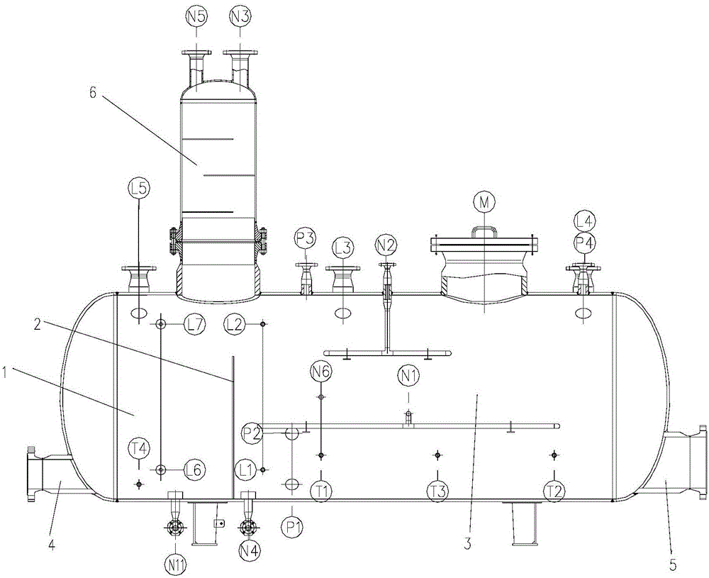
[0031] Such as figure 1 As shown, the urea catalytic hydrolysis reactor heated by double chambers provided by the present invention includes a blowdown chamber 1 ; a baffle plate 2 ; and a reaction chamber 3 . In this embodiment, the volume of the urea catalytic hydrolysis reactor is 5.9 cubic meters, 1400mm high, and the height of the baffle plate is 980mm, because the liquid level inside the reactor will be half of the height of the reactor, so the height of the baffle plate should be high half the height of the reactor. U-shaped heating coils are installed at the bottoms of the sewage chamber 1 and the reaction chamber 3, and the liquid level in the reactor should be higher than the U-shaped heating coils at this time.

[0032] Step 1: Add 25% (calculated by volume) desalted water into the empty reactor through the urea solution inlet N1 into the reaction chamber 3 to make the liquid level reach 350 mm.

[0033] Step 2: A certain amount of catalyst dissolved in urea solut...


PUM


Abstract

The invention discloses a double air chamber heated urea catalytic hydrolysis reactor and a method. The urea catalytic hydrolysis reactor comprises a reaction chamber and a sewage discharge chamber. The liquid level of the reaction chamber is raised regularly to discharge the upper layer sewage containing liquid into the sewage discharge chamber, the blowdown liquid is subjected to secondary decomposition in the sewage discharge chamber and then discharged, and the two chambers are both equipped with a heating coil, thus achieving sewage discharge and efficient use of energy.

Description

technical field [0001] The invention belongs to the technical field of air pollution control, and relates to a hydrolysis reactor for denitrifying coal-fired flue gas of a thermal power plant by utilizing ammonia gas generated by catalytic hydrolysis of urea, in particular to a urea catalytic hydrolysis reactor and a method heated by double gas chambers. technical background [0002] Flue gas denitrification refers to the technology for removing the harmful substance-NOX contained in the flue gas after high-temperature combustion (including coal-fired boilers, oil-fired gas-fired boilers and some industrial furnaces), including SCR and SNCR. SCR is the mainstream technology for flue gas denitrification. The so-called SCR technology refers to installing an SCR reactor between the economizer and the air preheater of the boiler, installing a catalyst in the reactor, injecting a reducing agent (ammonia-containing gas) into the flue section before the reactor, reducing The catal...

Claims


Application Information

Patent Timeline
IPC IPC(8): C01C1/08
Inventor 孟磊李春雨肖志均丁艳军刘东旭
Owner DATANG ENVIRONMENT IND GRP
Learn More