A ceramic fiber waste slag cotton mixing and shearing separator

A ceramic fiber and separator technology, which is applied in the field of shear separator, can solve the problems of affecting cotton fiber quality, unreasonable structure, and low production effect, and achieve the effects of saving labor, improving production efficiency, and saving costs

Active Publication Date: 2017-07-21
山东红阳高温节能材料股份有限公司
View PDF1 Cites 0 Cited by
  • Summary
  • Abstract
  • Description
  • Claims
  • Application Information

AI Technical Summary

Problems solved by technology

[0003] The Chinese patent with the publication number CN102199812A published on September 28, 2011 proposes an impurity separation mechanism under the machine for waste cotton, wool, and hemp, which solves the problem of cleaning devices when the existing waste cotton, wool, and hemp are recovered and cleaned. Unreasonable structure leads to large power consumption, low production effect and affects the quality of cotton fiber

Method used


Image

  • A ceramic fiber waste slag cotton mixing and shearing separator
  • A ceramic fiber waste slag cotton mixing and shearing separator
  • A ceramic fiber waste slag cotton mixing and shearing separator

Examples


Embodiment

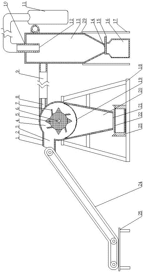
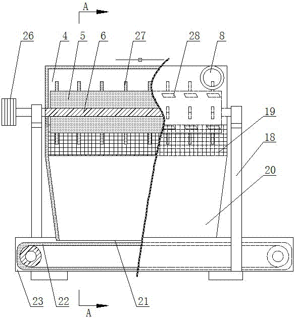
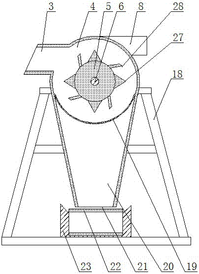
[0031] The ceramic fiber waste slag cotton blending shearing separator of the present invention includes a bracket I18, a feeding conveyor 24, a shearing separator 1, a discharge conveyor 22, a collecting device 29, a charging bag 5, a motor unit, The electric control box, the shearing separator 1 is fixed on the bracket I18. The shearing separator 1 includes a casing 2, a rotor 5, a rotating shaft 6, a number of blades 7, and a screen 19. The casing 2 forms a connected shearing separation chamber 4, The slag bin 20, specifically, the cross section of the shear separation chamber 4 is arc-shaped, the shear separation chamber 4 and the side wall of the slag bin 20 intersect tangentially, and the shear separation chamber 4 is provided with a feed port 3 and a discharge port 8. The slag bin 20 has a slag outlet 21, the shear separation chamber 4 and the lower slag bin 20 are separated by a screen 19, and the rotating shaft 6 is located in the shear separation chamber 4 and is fixed...


PUM


Abstract

The invention discloses a shearing and separating machine for mixed materials of waste slag and waste cotton of ceramic fibers and belongs to the field of shearing and separating machines. The shearing and separating machine aims at achieving separation and recycle of mixed materials of the waste slag and waste cotton of the ceramic fibers. The shearing and separating machine comprises a support I, a feeding conveyor, a shearing and separating machine body, a discharging conveyor, a collecting device, a motor unit and an electric cabinet; the shearing and separating machine body is fixed to the support I; the shearing and separating machine body comprises a shell, a rotor, a rotating shaft, a plurality of blades and a screen; the shell forms a shearing and separating cavity and a slag bin which are communicated with each other; a feeding port and a discharging port are formed in the shearing and separating cavity; a slag discharging port is formed in the slag bin; the shearing and separating cavity is isolated from the slag bin located below the shearing and separating cavity through the screen; the rotating shaft is arranged inside the shearing and separating cavity; the rotor is arranged on the periphery of the rotating shaft; the blades are arranged on the outer side face of the rotor; the motor unit is connected with and drives the feeding conveyor, the discharging conveyor and the rotating shaft; the feeding conveyor is communicated with the feeding port; the discharging conveyor is located below the slag discharging port; the discharging port is communicated with the collecting device.

Description

Technical field [0001] The invention relates to a shearing separator, in particular to a ceramic fiber waste slag cotton blending shearing separator. Background technique [0002] Ceramic fiber is a kind of fibrous lightweight refractory material. It has the advantages of light weight, high temperature resistance, good thermal stability, low thermal conductivity, small specific heat and mechanical vibration resistance. It is used in machinery, metallurgy, chemical industry, petroleum, ceramics, glass , Electronics and other industries have been widely used. Compared with traditional refractory materials such as thermal insulation bricks and castables, ceramic fiber can save energy by 10-30%. It has a wide range of applications and a large amount of use. In the production process, there is still a large amount of reusable long-fiber waste cotton in the waste residue, cotton waste, and leftover material. How to separate the useable long-fiber waste cotton from the waste slag cotto...

Claims


Application Information

Patent Timeline
Patent Type & Authority Patents(China)
IPC IPC(8): B29B17/00B29B17/04B29B17/02
CPCY02W30/52Y02W30/62
Inventor 孙选郑志永吕光耀
Owner 山东红阳高温节能材料股份有限公司
Why Eureka
Try Eureka