
High-precision control method for double-frame mscmg frame system based on adaptive sliding mode compensation

An adaptive sliding mode and frame system technology, applied in the field of servo system control, can solve problems such as difficult system dynamics, decoupling stability to be studied, and large computing resources

Active Publication Date: 2017-03-22
BEIHANG UNIV
View PDF5 Cites 0 Cited by
  • Summary
  • Abstract
  • Description
  • Claims
  • Application Information

AI Technical Summary

Problems solved by technology

Intelligent decoupling does not depend on the system model, mainly including neural network decoupling, least squares support vector machine, fuzzy decoupling, etc. Neural network decoupling solves the problem that the dynamic inversion of the system is difficult to achieve, due to its strong self-learning ability , can obtain stronger robustness; compared with the neural network, the least squares support vector machine adopts the structured risk minimization criterion, and there is no local minimum problem; fuzzy decoupling is a robust solution that is not sensitive to parameters Coupling method, but it needs manual induction and summary of operating experience on the controlled object, and decoupling stability needs to be studied
The ubiquitous problem of intelligent linearized decoupling control is that the control algorithm is complex and requires a large amount of computing resources, which is not conducive to engineering practice
State feedback linearization is mainly divided into dynamic inverse system decoupling and differential geometry method decoupling. The dynamic inverse system method must ensure the reversibility of the system, while the differential geometry method must ensure that the system can be described as an affine transformation mode, and the frame system is reversible. Proof of property and dynamic inverse solution process are more complex

Method used


Image

  • High-precision control method for double-frame mscmg frame system based on adaptive sliding mode compensation
  • High-precision control method for double-frame mscmg frame system based on adaptive sliding mode compensation
  • High-precision control method for double-frame mscmg frame system based on adaptive sliding mode compensation

Examples


specific Embodiment approach

[0060] (1) Establish the dynamic model of the double frame servo system

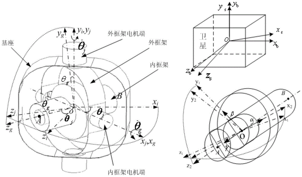
[0061] The coordinates of the maglev control moment gyro frame system are defined as image 3 shown. ox i the y i z i is the inertial coordinate system, o is the geometric center of the gyroscope stator, x i In the initial state, coincide with the axis of the frame, and take the motor end of the frame as the positive direction, y i In the initial state, it points to the direction of the rotor rotation axis, z i In the initial state, it points to the direction of the rotor rotation axis; o s x s the y s z s is the installation reference coordinate system of the magnetic levitation control moment gyro, that is, the zero position coordinate system; o b x b the y b z b is the satellite body coordinate system; ox j the y j z j It is the coordinate system of the outer frame, which is fixedly connected with the outer frame, coincides with the zero position system at zero position, and has relati...


PUM


Abstract

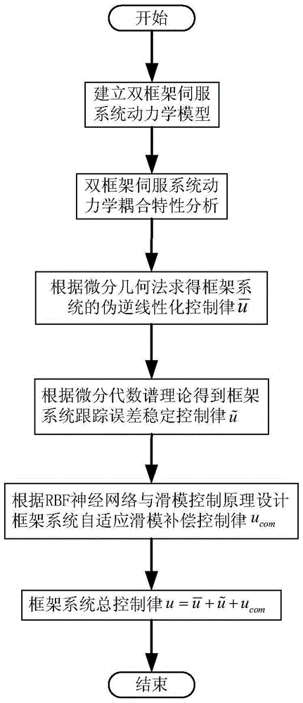
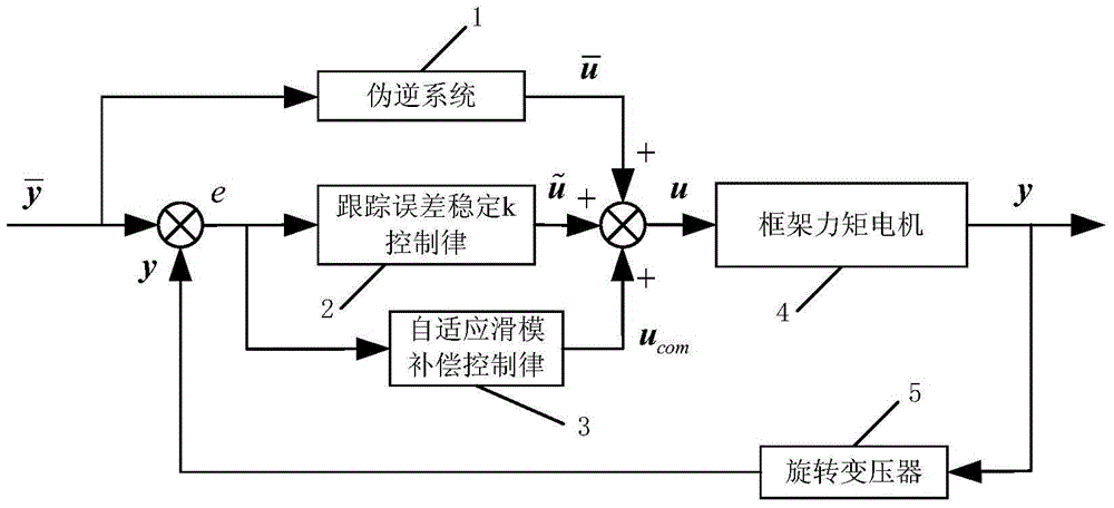
The invention discloses a dual-frame MSCMG frame system high-precision control method based on self-adaptive sliding mode compensation. Firstly, a dual-frame servosystem kinetic model is established; Input and output inverse mapping of a frame system is derived in a differential geometry approach, and then a a pseudo-inverse system of a frame system is obtained so as to realize kinetic decoupling control of the frame system and eliminate influences by coupling moments between frames; then on the basis of a differential algebraic spectrum theory, a tracking error stable control law is derived so as to enable the frame system to have certain response characteristics and guarantee the stability of the frame system; and finally, on the basis of an RBF neural network and a sliding mode control theory, a self-adaptive sliding mode compensation controller is designed to carry out compensation control on residual coupling, involved toques and nonlinear friction to enhance the disturbance inhibition ability of the frame system to realize high-precision angular rate tracking control of the dual-frame system. The method of the invention is simple and is simple to implement. The method is applicable to high-precision decoupling control of the dual-frame Magnetically Suspended Control Moment Gyroscope frame servosystem.

Description

technical field [0001] The invention belongs to the field of servo system control, and in particular relates to a high-precision control method for a dual-frame MSCMG (Magnetically Suspended Control Moment Gyro) frame system based on adaptive sliding mode compensation. The control method is based on adaptive sliding mode compensation control for realizing frame The high-precision angular rate tracking control of the servo system improves the disturbance suppression ability of the frame system and realizes the high-precision torque output of the control torque gyro. Background technique [0002] The magnetic levitation control torque gyroscope is mainly composed of a high-speed rotor and a frame servo system. According to the degree of freedom of the frame, it can be divided into a single frame control torque gyroscope and a double frame control torque gyroscope. The torque output of four degrees of freedom is an important direction for the development of CMG (Control moment ...

Claims


Application Information

Patent Timeline
Patent Type & Authority Patents(China)
IPC IPC(8): G05D17/02
Inventor 崔培玲杨珊房建成李海涛宁欣闫斌
Owner BEIHANG UNIV
Learn More