Solar thermal power generation composite backboard and preparation method

A composite material, photothermal power generation technology, applied in solar thermal power generation, lighting and heating equipment, optics, etc., can solve problems such as time-consuming and laborious on-site light concentration adjustment, poor temperature and weather resistance of steel plates, and unfavorable mass production. Achieve the effect of low cost, improved service life and convenient assembly

Active Publication Date: 2015-12-02
JIANGSU YUEKE NEW MATERIAL
View PDF5 Cites 3 Cited by
  • Summary
  • Abstract
  • Description
  • Claims
  • Application Information

AI Technical Summary

Problems solved by technology

[0005] The existing disc-shaped photothermal power generation backplane is generally composed of a steel plate and a reflective mirror attached to the steel plate. It has a strong structural strength and has a relatively outstanding effect in terms of wind resistance and deformation, but the overall weight is heavy and the transportation is not large. Convenient, and the temperature and weather resistance of the steel plate is poor, which is not conducive to long-term use
According to the solar concentrating disc published in the 2012 No. 2 "Solar Concentrating Disc Technology Development Status" of "Leader", the concentrating disc emitter mirror group composed of 82 concentrating mirrors is used, and the total reflection area is 87.82.m 2 , the weight of the entire concentrator reaches 7257kg, which is not conducive to mass production, and the on-site concentrator adjustment is time-consuming and laborious

Method used


Image

  • Solar thermal power generation composite backboard and preparation method
  • Solar thermal power generation composite backboard and preparation method

Examples


Embodiment 1

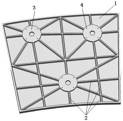
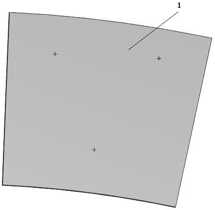
[0029] Such as figure 1 and 2 As shown, a photothermal power generation composite material backplane includes a backplane 1 and a reflective mirror laid on one side of the backplane. The other side of the backplane 1 is provided with a plurality of ribs 2 and a plurality of connecting discs. 3. The ribs 2 extend from the edge of the connecting disc 3 to the edge of the back plate 1 . A plurality of nuts 4 are arranged on the connecting disk 3 . The backplane 1 and the connection disc 3 are made of epoxy resin. Further, a reinforcing layer is arranged inside the backboard. Further, the reinforcement layer includes chopped strand mat, square cloth, triaxial cloth, and PVC sandwich foam laid sequentially from the outside to the inside. The setting of the reinforcement layer can enhance the strength of the composite material backplane, and protect the backplane structure from being damaged by particles such as external sand and gravel. Further preferably, the reinforcing rib...

Embodiment 2

[0035] Such as figure 1 and 2As shown, a photothermal power generation composite material backplane includes a backplane 1 and a reflective mirror laid on one side of the backplane. The other side of the backplane 1 is provided with a plurality of ribs 2 and a plurality of connecting discs. 3. The ribs 2 extend from the edge of the connecting disc 3 to the edge of the back plate 1 . A plurality of nuts 4 are arranged on the connecting disk 3 . The backplane 1 and the connection disc 3 are made of epoxy resin. Further, a reinforcing layer is arranged inside the backboard. Further, the reinforcement layer includes chopped strand mat, square cloth, triaxial cloth, and PVC sandwich foam laid sequentially from the outside to the inside. The setting of the reinforcement layer can enhance the strength of the composite material backplane, and protect the backplane structure from being damaged by particles such as external sand and gravel. Further preferably, the reinforcing ribs...

Embodiment 3

[0041] Such as figure 1 and 2 As shown, a photothermal power generation composite material backplane includes a backplane 1 and a reflective mirror laid on one side of the backplane. The other side of the backplane 1 is provided with a plurality of ribs 2 and a plurality of connecting discs. 3. The ribs 2 extend from the edge of the connecting disc 3 to the edge of the back plate 1 . A plurality of nuts 4 are arranged on the connecting disk 3 . The backplane 1 and the connection disc 3 are made of epoxy resin. Further, a reinforcing layer is arranged inside the backboard. Further, the reinforcement layer includes chopped strand mat, square cloth, triaxial cloth, and PVC sandwich foam laid sequentially from the outside to the inside. The setting of the reinforcement layer can enhance the strength of the composite material backplane, and protect the backplane structure from being damaged by particles such as external sand and gravel. Further preferably, the reinforcing rib...


PUM


Abstract

The invention relates to a solar thermal power generation composite backboard and a preparation method thereof. The composite backboard comprises a backboard and a reflective mirror laid on the backboard, wherein reinforcing ribs and a plurality of connecting discs which are integrally formed with the backboard are arranged on the backboard, the connecting discs and the reinforcing ribs are closely jointed, the backboard and the connecting discs are made of epoxy resin, firstly, the connecting discs are prepared in a mold, then reinforcing layer auxiliary materials, the reinforcing ribs, the connecting discs, vacuum auxiliary materials and the like are laid in the backboard mold as required, vacuum pouring of the epoxy resin is performed, the backboard integrally formed with the reinforcing ribs and the connecting discs is prepared after cooling forming, then reflective glass is bond to the backboard, and the composite backboard is prepared. Compared with the prior art, the composite backboard is uniform in structure, high in strength, low in cost, long in service life, simple in preparation technology and convenient to install.

Description

technical field [0001] The invention relates to a composite material backboard and a preparation method thereof, in particular to a photothermal power generation composite material backboard and a preparation method thereof. Background technique [0002] Solar energy has the characteristics of unlimited reserves, universal distribution, clean utilization, and economy. It is considered to be one of the new energy sources with the most development prospects and the best solution to the growing energy demand of future social development. [0003] Solar power generation is the main way to generate new energy by using solar energy, including photovoltaic power generation and photothermal power generation. Among them, solar thermal power generation has better adaptability to grid load, high photoelectric conversion efficiency, and is easy to produce scale effects. The manufacturing process of consumables is more environmentally friendly and has good power adjustability, which is c...

Claims


Application Information

Patent Timeline
Patent Type & Authority Applications(China)
IPC IPC(8): G02B7/183F24J2/10F24J2/52F24S23/70
CPCG02B7/183F24S23/70F24S25/00Y02E10/47
Inventor 周利峰
Owner JIANGSU YUEKE NEW MATERIAL
Why Eureka
Try Eureka