
An ammeter terminal block

A terminal block and electric meter technology, applied in the measurement of electrical variables, measuring devices, instruments, etc., can solve problems such as low efficiency, cluttered and complex wiring harnesses, etc., and achieve the effect of reducing time consumption and improving product reliability.

Inactive Publication Date: 2015-12-02
杰特电子实业(深圳)有限公司
View PDF0 Cites 1 Cited by
  • Summary
  • Abstract
  • Description
  • Claims
  • Application Information

AI Technical Summary

Problems solved by technology

[0002] At present, the connection structure and electrical connection process between the gold finger part of the PCB board and the terminal block of the electric meter on the market use multiple wires to connect the terminal block. It can be seen that riveting is required during the connection process, and the structure of the connecting wire is complicated. The wiring harness is also relatively messy; for the meter terminal block, the terminal block body is used for the assembly and electrical connection of the PCB board on the one hand, and on the other hand for the assembly and electrical connection of the external wire; its use is very wide; the traditional The defects of the PCB board connection structure caused inefficiency in our actual assembly and production, and when in use, due to too many riveting positions and connections, the entire meter was unstable; After the table body is connected to the external wire, the whole instability factor will be greatly increased. If the meter is used in some occasions with slight vibration, the external wire and the connection of the PCB board will be easily loosened, resulting in the failure of the meter

Method used


Image

  • An ammeter terminal block
  • An ammeter terminal block
  • An ammeter terminal block

Examples


specific Embodiment approach

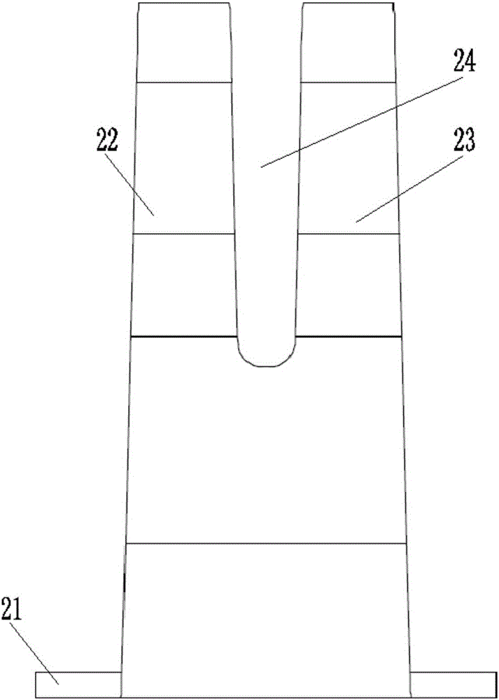
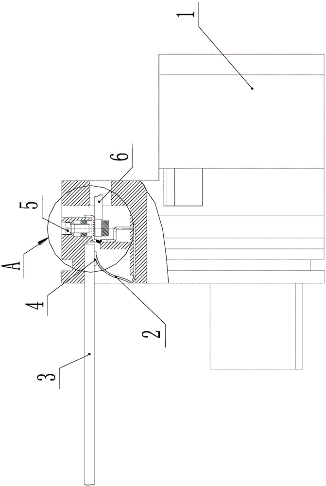
[0028] Such as Figure 1-5 As shown, it shows a specific embodiment of the present invention, as shown in the figure, the present invention is an ammeter terminal block, which is used to connect with a PCB board 3; it includes a terminal block body 1 and a double contact shrapnel 2; the terminal There is a mounting groove on the body of the terminal, and the lower end of the double-contact shrapnel is fixedly installed in the mounting groove on the body of the terminal block; pads 4 are evenly distributed on the PCB along the width direction of the PCB, correspondingly, the The double-contact shrapnel 2 are evenly distributed in the installation groove; the pads are soldered and installed on the bottom surface of the PCB; between the tank walls at the top;

[0029] As shown in the figure, the terminal block body is also provided with a mounting hole for assembling wires; a crimping frame 7 is provided in the mounting hole; Square hole 72; there is a threaded hole on the top ...


PUM


Abstract

The invention discloses an ammeter terminal block comprising a terminal block body and double contact leaf springs. The terminal block body is provided with an installation groove. The lower end of the double contact spring is fixedly installed in the installation groove of the terminal block body. Welding discs are uniformly distributed on a PCB in the width direction of the PCB. Correspondingly, the double contact leaf springs are uniformly distributed in the installation groove. The welding discs are installed on the bottom surface of the PCB. The PCB is connected into the installation groove in an inserted mode, and is positioned between the top ends of the double contact leaf springs and the groove wall of the top portion of the installation groove. The terminal block body is also provided with an installing hole used for assembling of a conductive wire; a wire pressing frame is arranged in the installing hole; the wire pressing frame is provided with a penetrating square hole used for accommodating a conducting strip and the conductive wire; the wire pressing frame is provided with a threaded hole matched with screw threads of a screw; and the top wall of the wire pressing frame is provided with an inverted-V-shaped groove in a penetrating mode.

Description

technical field [0001] The invention relates to a terminal block of an electric meter, which is used for realizing the connection between a PCB board of the electric meter and a terminal block body. Background technique [0002] At present, the connection structure and electrical connection process between the gold finger part of the PCB board and the terminal block of the electric meter on the market use multiple wires to connect the terminal block. It can be seen that riveting is required during the connection process, and the structure of the connecting wire is complicated. The wiring harness is also relatively messy; for the meter terminal block, the terminal block body is used for the assembly and electrical connection of the PCB board on the one hand, and on the other hand for the assembly and electrical connection of the external wire; its use is very wide; the traditional The defects of the PCB board connection structure caused inefficiency in our actual assembly and...

Claims


Application Information

Patent Timeline
IPC IPC(8): G01R11/04
Inventor 刘志坚
Owner 杰特电子实业(深圳)有限公司
Learn More