A micro-convective radiation cooling and heating ceiling device

A ceiling, cooling and heating technology, applied in the field of micro-convection radiation cooling and heating ceiling devices, can solve the problems of low comfort, high energy consumption and high production cost of indoor heat exchange devices, and achieves improving indoor comfort, reducing energy consumption and reducing heat transfer. wasteful effect

Active Publication Date: 2018-04-03
KRUEGER AIR CONDITIONING TECH BEIJING
View PDF5 Cites 1 Cited by
  • Summary
  • Abstract
  • Description
  • Claims
  • Application Information

AI Technical Summary

Problems solved by technology

[0003] The purpose of the present invention is to overcome the above-mentioned technical deficiencies, and propose a micro-convective radiation heating and cooling ceiling device, which solves the technical problems of low comfort, high energy consumption, easy condensation, and high production cost of indoor heat exchange devices in the prior art, and at the same time can Utilize existing mature building decoration ceiling materials

Method used


Image

  • A micro-convective radiation cooling and heating ceiling device
  • A micro-convective radiation cooling and heating ceiling device
  • A micro-convective radiation cooling and heating ceiling device

Examples


Embodiment 1

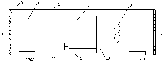
[0034] Such as figure 1 , figure 2 , Figure 5 As shown, Embodiment 1 of the present invention provides a kind of micro-convection radiation heating and cooling ceiling device, comprising:

[0035] Insulation board 1;

[0036] The ceiling board 2 arranged under the insulation board 1, the outer edge of the ceiling board 2 is connected with the outer edge of the insulation board 1 through the connector 3 to form a sealed space, and the ceiling board 2 is provided with a pair of air inlets 201 and a pair of air outlets 202;

[0037] The connecting plate 4 located in the sealed space, the upper and lower ends of the connecting plate 4 are respectively connected with the insulation board 1 and the ceiling plate 2, and the sealed space is divided into a circulation space 5 and a heat exchange space. The exchange space 6, and the connecting plate 4 is provided with a circulation air inlet 401 and a circulation air outlet 402;

[0038] The coil pipe 7 arranged in the exchange s...

Embodiment 2

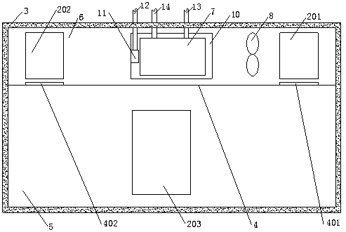
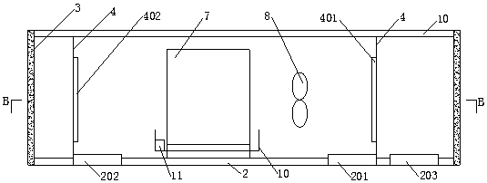
[0059] This embodiment 2 is basically the same as the above-mentioned embodiment 1, the difference is that, as image 3 , Figure 4 As shown, the connecting plate 4 of the present embodiment is in the shape of a rectangular ring, and the connecting plate 4 divides the sealed space into a rectangular exchange space 6 and an annular circulation space 5 surrounding the exchange space 6. The convection air inlet 201 The circulation air inlet 401 and the circulation air outlet 402 are symmetrically arranged on the circulation space 5 . By setting the rectangular ring-shaped connection plate 4, on the one hand, the area of ​​the connection plate 4 is increased, that is, the contact area between the exchange space 6 and the circulation space 5 is increased, which is beneficial to the heat transfer between the exchange space 6 and the circulation space 5 directly through the connection plate 4, On the other hand, airflow passages are formed on both sides of the exchange space 6, whic...


PUM


Abstract

The invention discloses a micro-convection cooling and radiation heating ceiling device which comprises a heat preservation board, a ceiling board, a connecting board, a coiled pipe and a draught fan. The outer edge of the ceiling board is connected with the outer edge of the heat preservation board through a connecting body to form a sealed space. A convection gas inlet and a convection gas outlet are formed in the ceiling board. The upper end and the lower end of the connecting plate are connected with the heat preservation board and the ceiling board respectively. The sealed space is divided by the connecting plate into a circulation space and an exchange space for heat exchange. A circulation gas inlet and a circulation gas outlet are formed in the connecting plate. The coiled pipe and the draught fan are arranged in the exchange space. By arranging the heat preservation board on the ceiling board to achieve thermal insulation, heat transfer waste is reduced; meanwhile, by achieving convection rapid heat exchange through a convection channel and achieving radiation heat exchange through a circulation channel, the flow of a working medium in the coiled pipe and the air volume of the draught fan are reduced during radiation heat exchange, the indoor comfort level is increased, and meanwhile energy consumption is lowered; in addition, the temperature difference between the upper side and the lower side of the ceiling board is small through convection heat exchange in the early period, and therefore dew formation can be effectively avoided through radiation heat exchange in the later period.

Description

technical field [0001] The invention relates to the technical field of air conditioning cooling and heating radiation, in particular to a micro-convection radiation cooling and heating ceiling device. Background technique [0002] In the field of cooling, heating, ventilation and purification of air conditioners, in order to solve the problem of warming in winter and cool in summer in rooms or local spaces, the current method is to either adopt convective heat exchange with finned coils and fan circulation, or use built-in or composite The radiant panel method of the coil. However, it is not very reasonable to consider the construction of indoor thermal comfort environment, energy saving, and the optimization of building interior decoration materials and equipment. If the convection method of finned coil plus fan has a blowing feeling and low comfort, the temperature of the cold and hot working fluid in the coil must be higher or lower than the sufficient value in the air-c...

Claims


Application Information

Patent Timeline
Patent Type & Authority Patents(China)
IPC IPC(8): F24F5/00F24F13/02F24F13/068E04B9/02
CPCE04B9/02F24F5/0092F24F13/0227F24F13/068
Inventor 谈太明代伯清李兵兵
Owner KRUEGER AIR CONDITIONING TECH BEIJING
Why Eureka
Try Eureka