Bearing and deep-well pump transmission shaft system provided with bearing

A technology for transmission shafts and deep well pumps, which is applied to the rigid support of bearing components, bearing elements, shafts and bearings, etc., which can solve problems such as the inability to meet the vibration reduction requirements of long transmission shafts, and avoid insufficient lubrication, The effect of improving safety performance

Active Publication Date: 2015-12-02
WUHAN MARINE MACHINERY PLANT
View PDF9 Cites 5 Cited by
  • Summary
  • Abstract
  • Description
  • Claims
  • Application Information

AI Technical Summary

Problems solved by technology

[0005] In order to solve the problem that the existing bearings cannot meet the vibration reduction requirements of the transmission shaft with a long length

Method used


Image

  • Bearing and deep-well pump transmission shaft system provided with bearing
  • Bearing and deep-well pump transmission shaft system provided with bearing
  • Bearing and deep-well pump transmission shaft system provided with bearing

Examples


Embodiment 1

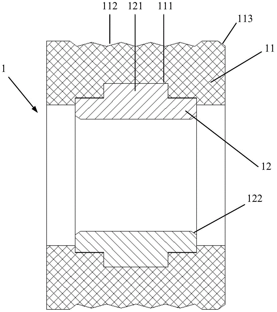
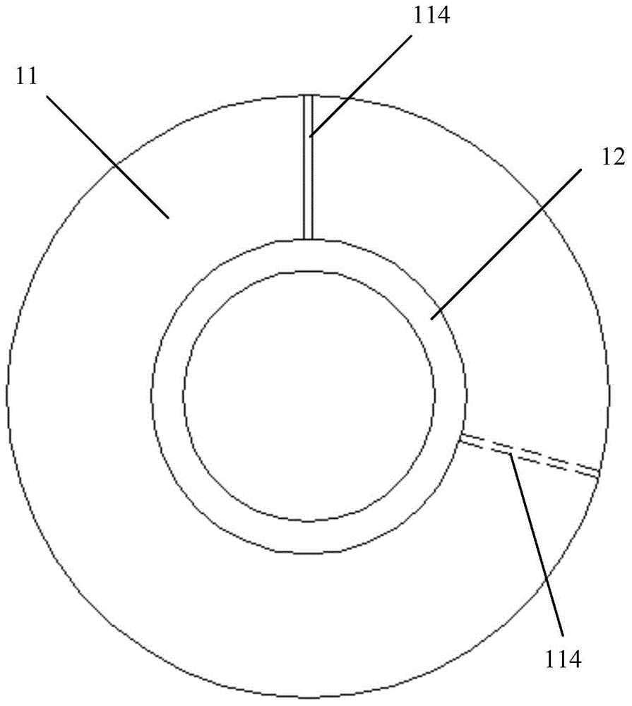
[0030] The embodiment of the present invention provides a bearing, such as figure 1 As shown, the bearing 1 includes a cylindrical outer sleeve 11 for connecting with the outer shaft tube (not shown) of the transmission shaft system and a circular cylindrical sleeve 11 for connecting with the major axis of the transmission shaft system (not shown). The cylindrical inner sleeve 12, the outer peripheral wall of the outer sleeve 11 is provided with a plurality of oil seepage annular grooves 112 arranged at intervals in the axial direction, and the inner peripheral wall of the outer sleeve 11 is provided with a ring for connecting the outer sleeve 11 and the inner sleeve. The clamping annular groove 111 of the shaft sleeve 12, the outer peripheral wall of the inner sleeve 12 is provided with a clamping protrusion 121 matched with the clamping annular groove 111, and the inner sleeve 12 is connected by the clamping protrusion 121 and the clamping The annular groove 111 is fixedly i...

Embodiment 2

[0040] The embodiment of the present invention provides a deep well pump drive shaft system, see image 3 , the transmission shaft system includes a long shaft 2, an outer shaft tube 3, and at least one bearing 1 provided by Embodiment 1, the long shaft 2 is rotatably coaxially inserted in the bearing 1, and the outer shaft tube 3 is sleeved on the bearing 1, the bearing 1 is sandwiched between the outer shaft tube 3 and the long shaft 2. The bearing 1 is arranged between the outer shaft tube 3 and the long shaft 2, which not only reduces the mechanical vibration of the transmission shaft, but also increases the structural stability of the transmission shaft, so that the upper limit of the length and the rigidity of the transmission shaft are improved.

[0041] In the embodiment of the present invention, the outer shaft tube 3 and the bearing 1 are in interference fit, because the outer shaft sleeve 11 of the bearing 1 is a fluorine rubber sleeve, so the elasticity between the...


PUM


Abstract

The invention discloses a bearing and a deep-well pump transmission shaft system provided with the bearing, and belongs to the technical field of bearing machines. The bearing comprises an outer shaft sleeve and an inner shaft sleeve, wherein the outer shaft sleeve is arranged on the outer side of the inner shaft sleeve; a plurality of spaced oil seeping annular grooves are axially formed in the outer peripheral wall of the outer shaft sleeve; clamping annular grooves used for connecting the outer shaft sleeve to the inner shaft sleeve are formed in the inner peripheral wall of the outer shaft sleeve; clamping convex blocks matched with the clamping annular grooves are arranged on the outer peripheral wall of the inner shaft sleeve; the outer shaft sleeve is used to be matched with an outer shaft pipe of the transmission shaft system; the inner shaft sleeve is used to be matched with a long shaft of the transmission shaft system; a first plug-in mounting oblique surface is arranged in a position of one end, corresponding to the outer peripheral wall of the outer shaft sleeve, of the outer shaft sleeve; second plug-in mounting oblique surfaces are arranged in he positions of the two ends, corresponding to the inner peripheral wall of the inner shaft sleeve, of the inner shaft sleeve; and oil seeping notches are formed in the positions of the two ends, corresponding to the end faces of the outer shaft sleeve, of the outer shaft sleeve. The bearing and the deep-well pump transmission shaft system can effectively exert a vibration reduction function; a high temperature situation caused by insufficient lubrication of the transmission shaft system is avoided; and the safety performance is improved accordingly.

Description

technical field [0001] The invention belongs to the technical field of bearing machinery, in particular to a bearing and a deep well pump transmission shaft system with the bearing. Background technique [0002] A deep well pump is a device used to pump liquid cargo from the liquid cargo tank to the outside of the liquid cargo tank. A common deep well pump usually includes a pump body placed in the cargo tank, a motor placed outside the cargo tank, and a drive shaft set between the pump body and the motor. The drive shaft is used to transmit the power output by the motor to the pump. The transmission shaft system includes a major shaft and an outer shaft tube sleeved outside the major shaft, and a bearing is arranged between the outer shaft tube and the major shaft. [0003] In the process of realizing the present invention, the inventor finds that there are at least the following problems in the prior art: [0004] Since the liquid cargo tank is usually loaded with flamma...

Claims


Application Information

Patent Timeline
IPC IPC(8): F16C33/04F16C33/20F16C35/10F16N1/00F04D29/046
Inventor 白俊江陈斌李战万晓红
Owner WUHAN MARINE MACHINERY PLANT
Why Eureka
Try Eureka