A ccus system based on gas lift method and its application

A gas lift method and gas lift well technology, applied in the fields of fluid extraction, earthwork drilling, climate sustainability, etc., can solve problems such as increasing operating costs, failure of oil wells to inject thermal fluid without stopping production, and increased greenhouse gas emissions , to achieve the effects of saving production costs, benefiting environmental protection, and convenient recycling

Active Publication Date: 2018-04-27
CHINA UNIV OF PETROLEUM (EAST CHINA)
View PDF8 Cites 1 Cited by
  • Summary
  • Abstract
  • Description
  • Claims
  • Application Information

AI Technical Summary

Problems solved by technology

Due to the high wellhead casing pressure of gas lift wells, the oil wells cannot realize non-stop production and injection of hot fluid when the wax is removed by thermal washing, which affects the oil production rate
When the electric heating method is used to remove wax, since there is no sucker rod in the gas lift well, the wellbore or casing can only be used as the heating element in the circuit for electric heating, resulting in the need to stop production, replace the wellbore string or the casing string, increase operating costs
[0004] In addition, the thermal wax removal process inevitably uses coal, natural gas and other fossil fuels to provide thermal energy, resulting in increasing greenhouse gas emissions

Method used


Image

  • A ccus system based on gas lift method and its application
  • A ccus system based on gas lift method and its application
  • A ccus system based on gas lift method and its application

Examples


Embodiment 1

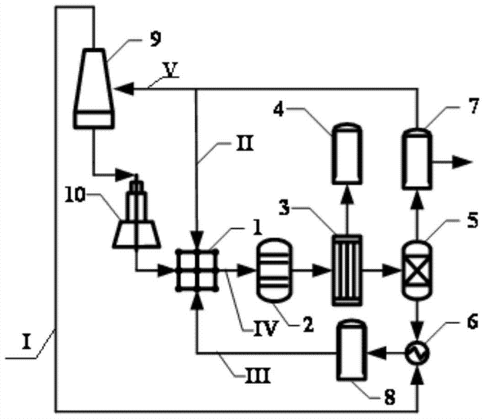
[0062] A CCUS system based on gas lift oil recovery, including production pipeline IV, carbon dioxide pipeline, natural gas pipeline, gas generator set 9 and electric heating wax removal and wax prevention device 10;

[0063] The production pipeline IV includes an oil-gas separation unit sequentially connected to the gas lift well group 1, a natural gas purification system 5, and a natural gas pipeline and a carbon dioxide pipeline respectively connected to the natural gas purification system 5;

[0064] The natural gas pipeline includes the natural gas pumping pipeline II for pumping natural gas into the gas lift well group 1, and also includes the natural gas transmission and power generation pipeline V for the gas-fired generator set 9 to generate electricity;

[0065] The carbon dioxide pipeline includes a carbon dioxide pumping pipeline III for pumping carbon dioxide into the gas lift well group 1, and also includes a carbon dioxide recovery pipeline I connected to the gas...

Embodiment 2

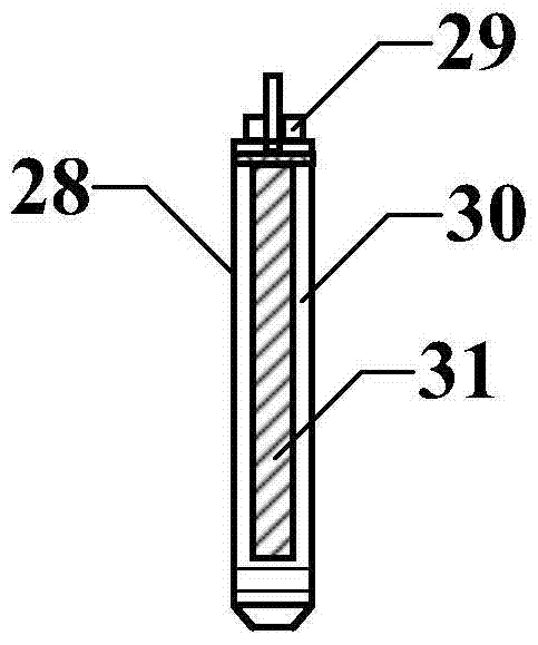
[0068] A CCUS system based on gas lift oil recovery as described in Embodiment 1, the difference is that the electric heating wax removal and anti-wax device 10 includes a steel armored cable 23 extending into the wellbore 22 through the sealing of the Christmas tree 19, so The steel armored cable 23 is powered by the gas generator set 9.

Embodiment 3

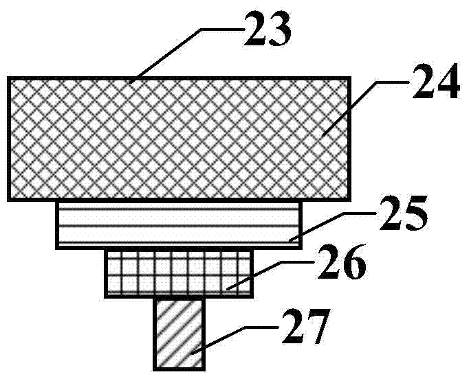
[0070] A kind of CCUS system based on gas lift oil recovery as described in Embodiment 2, the difference is that the steel armored cable 23 includes a steel armored sheath 24, an insulating material layer 25, a polytetrafluoro Vinyl layer 26 and cable core wire 27.


PUM


Abstract

A CCUS system and application based on gas lift oil recovery, including production pipelines, carbon dioxide pipelines, natural gas pipelines, gas-fired generator sets and electric heating paraffin removal devices, the gas source is separated into carbon dioxide and natural gas through the production pipelines , in which part of the natural gas is used for gas lift oil recovery for the gas lift well group, and the other part of the natural gas is used to supply power to the electric heating wax removal device through the gas generator set. This design not only reduces the power supply cost and technical difficulty of the ground power grid, but also reduces the The load of the power grid, but also enables the production of natural gas to be used near production; the carbon dioxide produced by oil production and the carbon dioxide discharged by the gas-fired generator set are uniformly used for the gas-lift oil recovery of the gas-lift well group, which greatly improves the regeneration of carbon dioxide efficiency and reduce carbon dioxide emissions.

Description

technical field [0001] The invention relates to a CCUS system for oil recovery based on a gas lift method and its application, and belongs to the technical field of wellbore wax removal and blocking removal, and carbon dioxide capture, utilization and storage. Background technique [0002] Gas lift oil recovery is a kind of oil recovery that relies on the mixing of high-pressure gas injected into the well from the surface and the fluid produced from the oil layer in the wellbore, and uses the expansion of the gas to reduce the density of the mixed liquid in the wellbore, and lifts the crude oil flowing into the well to the surface. Way. Gas lift recovery is one of the mechanical recovery methods that is more adaptable to oil well production conditions. It is often used in high-yield deep wells and oil wells with low sand content, low water content, high gas-oil ratio and low corrosive components. Gas lift production must have sufficient gas source, generally natural gas pro...

Claims


Application Information

Patent Timeline
Patent Type & Authority Patents(China)
IPC IPC(8): E21B43/16E21B36/04E21B37/00
CPCY02P90/70
Inventor 张超李兆敏李宾飞刘建林张新军刘己全董全伟
Owner CHINA UNIV OF PETROLEUM (EAST CHINA)
Why Eureka
Try Eureka