


Quick Research
Generate reliable direction feasibility study reports for your R&D in just a few steps.

Technical Q&A
Discover and master advanced knowledge NOW. Basics, ideas, possibilities, all at once.

Find Solutions
As an expert in R&D theories, this can generate solutions to your technical problems instantly.

Evaluate Feasibility
Analyze your overall solution with one click, know your potential R&D risks in advance.

Monitor Landscape
Get weekly tech updates, stay abreast of the latest tech innovations and key insights.
Construction method of constructional column constructed simultaneously with framework structure infill wall
A frame structure and construction method technology, applied in the direction of building structure, walls, building components, etc., can solve the problems of long construction period, complicated construction, poor quality, etc., and achieve the effect of low cost, convenient construction, and small thickness
- Summary
- Abstract
- Description
- Claims
- Application Information
AI Technical Summary
Benefits of technology
Problems solved by technology
Method used
Image


Examples
Embodiment Construction
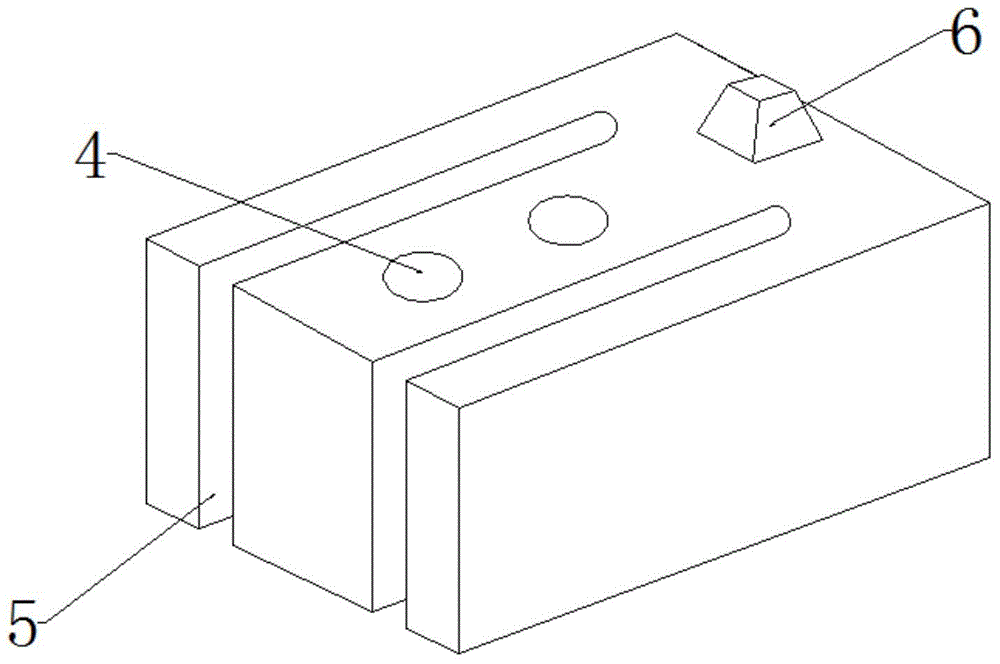
[0049] The present invention will be described below in conjunction with the accompanying drawings and specific embodiments, wherein the prefabricated section of the infill wall construction column and its construction method will be described in detail, and the T-shaped infill wall construction column and the cross-shaped infill wall construction column will be described in detail. A brief description of the prefabricated section and its construction method.
[0050] The construction of the prefabricated section combination and the new infill wall structure column includes the following steps:
[0051] 1. Embed four-hole embedded parts. In the preliminary construction, according to the design drawings, four-hole embedded parts were respectively embedded at the bottom surface and the top surface of the column where the structural column is set, to fix the longitudinal steel bars in the structural column.
[0052] 2. Fix the longitudinal reinforcement. According to the design...
PUM
| Property | Measurement | Unit |
|---|---|---|
| Side length | aaaaa | aaaaa |
| Thickness | aaaaa | aaaaa |
| Thickness | aaaaa | aaaaa |
Abstract
Description
Claims
Application Information
 - R&D Engineer
- R&D Manager
- IP Professional
- Industry Leading Data Capabilities
- Powerful AI technology
- Patent DNA Extraction
Browse by: Latest US Patents, China's latest patents, Technical Efficacy Thesaurus, Application Domain, Technology Topic, Popular Technical Reports.
© 2024 PatSnap. All rights reserved.Legal|Privacy policy|Modern Slavery Act Transparency Statement|Sitemap|About US| Contact US: help@patsnap.com